Device for detecting deposition rate of mortar

A deposition rate and mortar technology, applied in the analysis of materials, instruments, etc., can solve the problems of high relative viscosity of liquids, inconvenient monitoring, etc., and achieve the effects of reducing labor costs, avoiding recording errors, and improving detection stability

Inactive Publication Date: 2014-03-05
BAODING GUANGWEI GREEN ENERGY TECH CO LTD
View PDF7 Cites 0 Cited by
  • Summary
  • Abstract
  • Description
  • Claims
  • Application Information

AI Technical Summary

Problems solved by technology

[0010] 3) At room temperature, the relative viscosity of the liquid is high, and the free settling time is usually more than 2 days, which is not convenient for timely monitoring

Method used


Image

  • Device for detecting deposition rate of mortar
  • Device for detecting deposition rate of mortar

Examples


Embodiment Construction

[0028] The present invention will be further described below in conjunction with the accompanying drawings and embodiments.

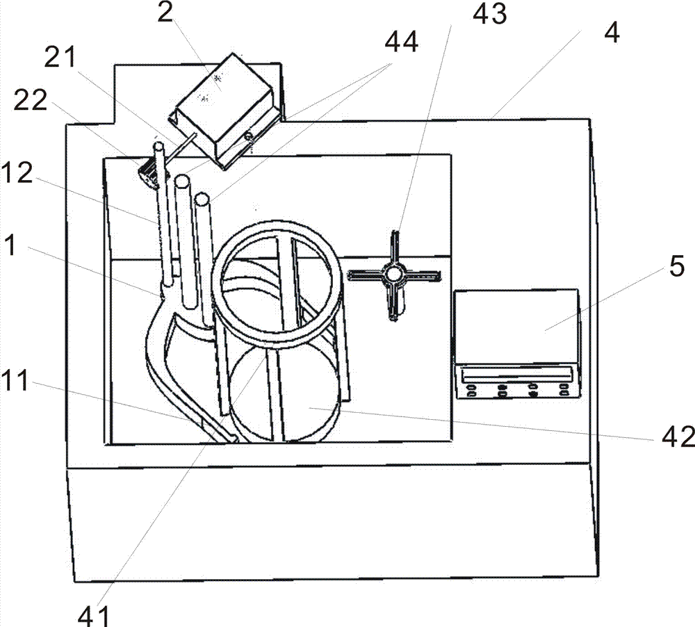
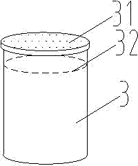
[0029] Such as figure 1 As shown, the present invention provides a device for detecting the rate of mortar deposition, including measuring cylinder 3 ( figure 1 Not shown in), infrared detector 1 and drive device 2; drive device 2 is connected with infrared detector 1, and infrared detector 1 can translate up and down; infrared detector 1 and drive device 2 are connected with central processing unit (in the figure not shown); the central processing unit controls the driving device 2 to drive the infrared detector 1 to move up and down according to the detection result of the infrared detector 1. Infrared detector 1 is in the shape of a "U", and the two arms of the "U" shape are an infrared transmitting end 11 with an infrared transmitter at the end and an infrared receiving end with an infrared receiver at the end, and the infrared transmitter and the ...


PUM


Abstract

The invention discloses a device for detecting a deposition rate of mortar. The device comprises a measurement barrel, an infrared detector and a driving device, wherein the driving device is connected with the infrared detector in a driving manner; the infrared detector can translate up and down; the infrared detector and the driving device are connected with a central processor; the infrared detector comprises an infrared emitting end and an infrared receiving end; the infrared emitting end and the infrared receiving end are positioned on the same horizontal plane, and a distance between the infrared emitting end and the infrared receiving end is not smaller than the outer diameter of the measurement barrel. According to the device for detecting the deposition rate of the mortar, the infrared detector is used for detecting and recording a boundary surface of a deposition layer and a supernatant liquid layer of cutting liquid, so that automatic detection is realized; the detection stability is improved, the labor cost is reduced; recording mistakes caused by a fact that a measurer awaits to detect the deposition rate for a long time are avoided.

Description

technical field [0001] The invention relates to the field of photovoltaics, in particular to a device for detecting the deposition rate of mortar in cutting fluid. Background technique [0002] The cutting of silicon material wafers in the photovoltaic industry adopts multi-wire cutting technology. The principle is: the ultra-fine cutting steel wire runs at high speed, driving the mortar (that is, cutting fluid) made of silicon carbide cutting edge and polyethylene glycol attached to the steel wire, so that the silicon carbide cutting edge is pressed tightly on the silicon block to be cut On the surface, under the high-speed operation of the steel wire, the hard characteristics and sharp water chestnuts of the silicon carbide particles grind the surface of the silicon block, thereby gradually cutting off the entire silicon rod. [0003] At present, most of the water-soluble cutting fluids widely used in the market are mainly composed of polyethylene glycol (PEG), and other ...

Claims


Application Information

Patent Timeline
Patent Type & Authority Applications(China)
IPC IPC(8): G01N15/04
Inventor 于琨王伟张兴亮
Owner BAODING GUANGWEI GREEN ENERGY TECH CO LTD
Why Eureka
Try Eureka