Embedded smart skin antenna

An intelligent skin antenna and embedded technology, applied in the electronic field, can solve the problems of small gain loss, short air standby time, performance degradation, etc., achieve dynamic reconfigurable electrical performance, self-diagnosis of working status, and reduce design scale Effect

Active Publication Date: 2014-03-05
10TH RES INST OF CETC
View PDF2 Cites 22 Cited by
  • Summary
  • Abstract
  • Description
  • Claims
  • Application Information

AI Technical Summary

Problems solved by technology

[0003] To sum up, how to realize the smart skin antenna has a small gain loss under the condition that the scanning angle is greater than ±45 degrees, and can realize the self-diagnosis of the working state of the antenna and the reconfigurable electrical performance of the antenna according to the change of the external electromagnetic environment, so as to achieve Intelligent, there is no definite design method
On existing aircraft, the antennas of the radar and communication systems often protrude from the surface of the airframe in the form of a knife-shaped or radome covering. The antennas protrude from the surface of the aircraft platform in large quantities and affect the aerodynamic/stealth performance of the aircraft, which not only destroys the aircraft The

Method used


Image

  • Embedded smart skin antenna
  • Embedded smart skin antenna
  • Embedded smart skin antenna

Examples


specific Embodiment approach

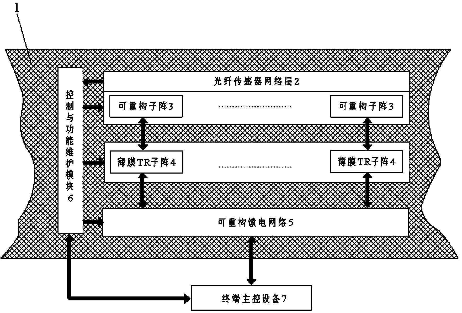
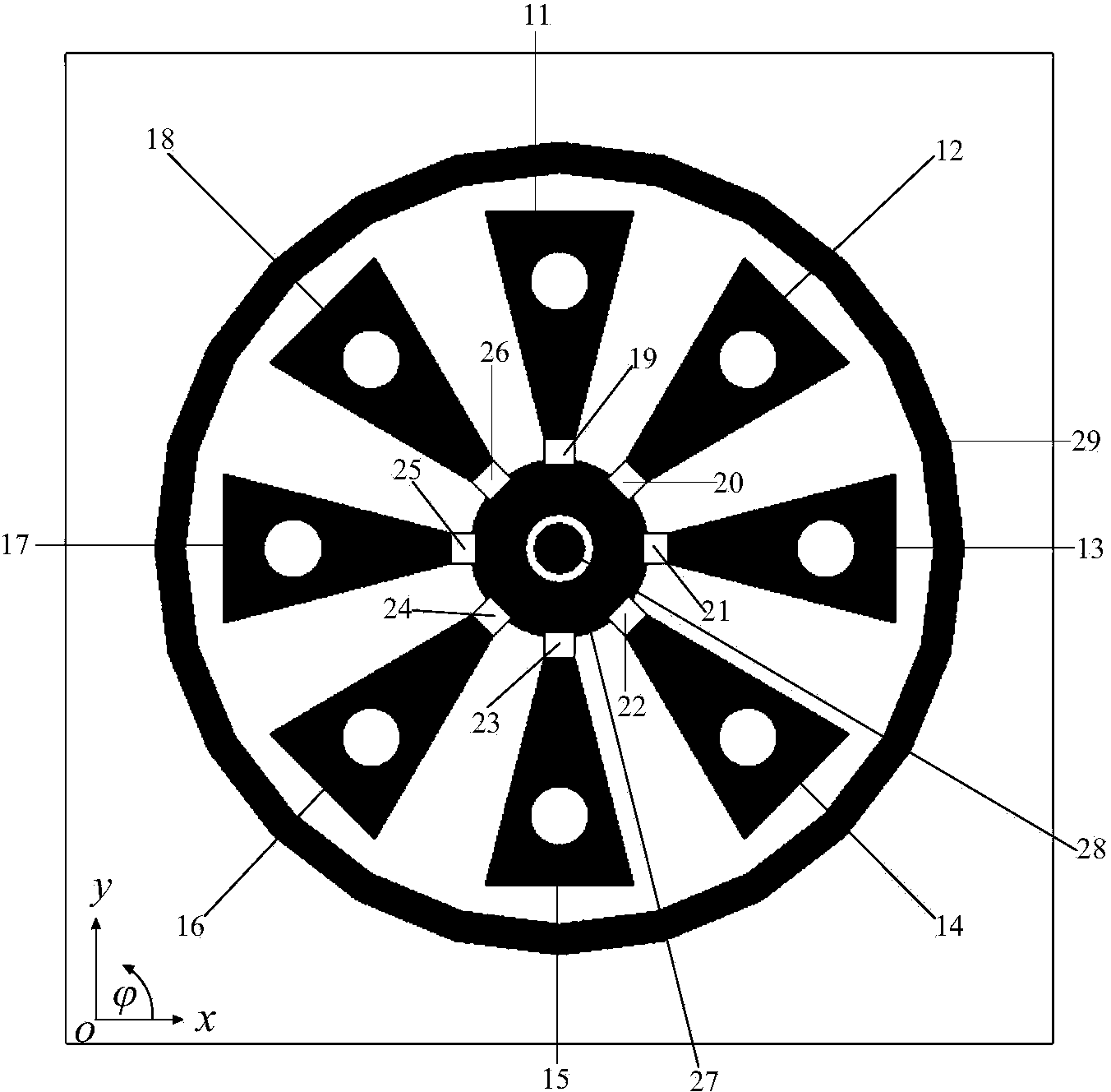
[0032] Step 4: Simultaneously with step 3, the function maintenance module 39 activates the reconfigurable sub-array control module 40 according to the user requirements of the terminal main control device 7, and directly controls the light guide of the reconfigurable antenna unit 10 of the reconfigurable sub-array 3 The working states of the switches 19 , 20 , 21 , 22 , 23 , 24 , 25 , and 26 complete the reconfiguration of the pattern of the reconfigurable antenna unit 10 in a specific scanning area. The specific implementation is as follows:

[0033] 1) When the embedded smart skin antenna beam points along θ0°~60°, During area scanning, the photoconductive switches 20 , 21 , and 22 of the reconfigurable antenna unit 10 are turned on, and the other five photoconductive switches are turned off, realizing the working state of the reconfigurable sub-array 3 at this time.

[0034] 2) When the embedded smart skin antenna beam points along θ=0°~60°, During area scanning, the p...


PUM


Abstract

The invention provides an embedded smart skin antenna which is formed by an optical fiber sensing network layer (2), a reconfigurable sub array (3), a thin film TR sub array (4), a reconfigurable feed network (5), and a control and function maintenance module (6). The optical fiber sensing network layer and the reconfigurable sub array are integrated as a whole, are sequentially and parallelly arranged with the thin film TR sub array (4) and the reconfigurable feed network in a laminated manner, and are jointly in parallel connection with the control and function maintenance module at the end. The control and function maintenance module, according to a user demand of a terminal main control device (7), sends a control instruction to the reconfigurable sub array, the thin film TR sub array, and the reconfigurable feed network; the working condition self-diagnosis of the embedded smart skin antenna and the electrical performance reconfiguration of the antenna are realized; the electric performance of the embedded smart skin antenna is ensured; and the defect that, after the sub array is partially damaged, a conventional antenna array is degraded in performance or cannot be reused is avoided. The embedded smart skin antenna also solves the defect that the array gain loss of a conventional phased array antenna is too large when the scanning angle theta is >= 45 DEG.

Description

technical field [0001] The invention belongs to the field of electronic technology, in particular to intelligent skin antenna technology and array antenna technology. Background technique [0002] An antenna called a "smart skin" is being developed in France due to the increasing communication capabilities of antennas. Intelligent skin technology is a new technology that integrates multiple disciplines such as materials, biology, photoelectric technology, automatic control and computer engineering. Smart material is a new type of functional material that can perceive external stimuli, judge and process them appropriately, and can be executed by itself. Smart materials are the fourth generation of materials following natural materials, synthetic polymer materials, and artificially designed materials. They are one of the important directions for the development of modern high-tech new materials. The boundaries between materials and structural materials are gradually disappea...

Claims


Application Information

Patent Timeline
IPC IPC(8): H01Q1/22H01Q1/28H01Q1/42H01Q13/08H01Q21/00H01Q25/00H01Q1/36H01Q3/24
Inventor 何庆强何海丹官正涛
Owner 10TH RES INST OF CETC
Why Eureka
Try Eureka