
Device for opening the suction depending on pressure

A suction part and pressure technology, which is applied to the power unit, the arrangement combined with the fuel supply of the internal combustion engine, and packaging, can solve the problems of unfavorable sealing of the check valve and loss of effective vacuum degree, and achieve the goal of small pressure loss and high efficiency Effect

Active Publication Date: 2016-04-06
KAUTEX TEXTRON
View PDF10 Cites 0 Cited by
  • Summary
  • Abstract
  • Description
  • Claims
  • Application Information

AI Technical Summary

Problems solved by technology

The state known in the art is: a check valve is arranged between the suction jet pump and the bubble extraction container, for example, the check valve is called a "fungus valve", a shortcoming of this check valve is, Part of the effective vacuum of the suction jet pump is lost due to the opening of the check valve
In order to reduce the loss of the effective vacuum of the suction jet pump, the closing force of the check valve is usually limited, but this is not good for the sealing of the check valve

Method used


Image

  • Device for opening the suction depending on pressure
  • Device for opening the suction depending on pressure

Examples


Embodiment Construction

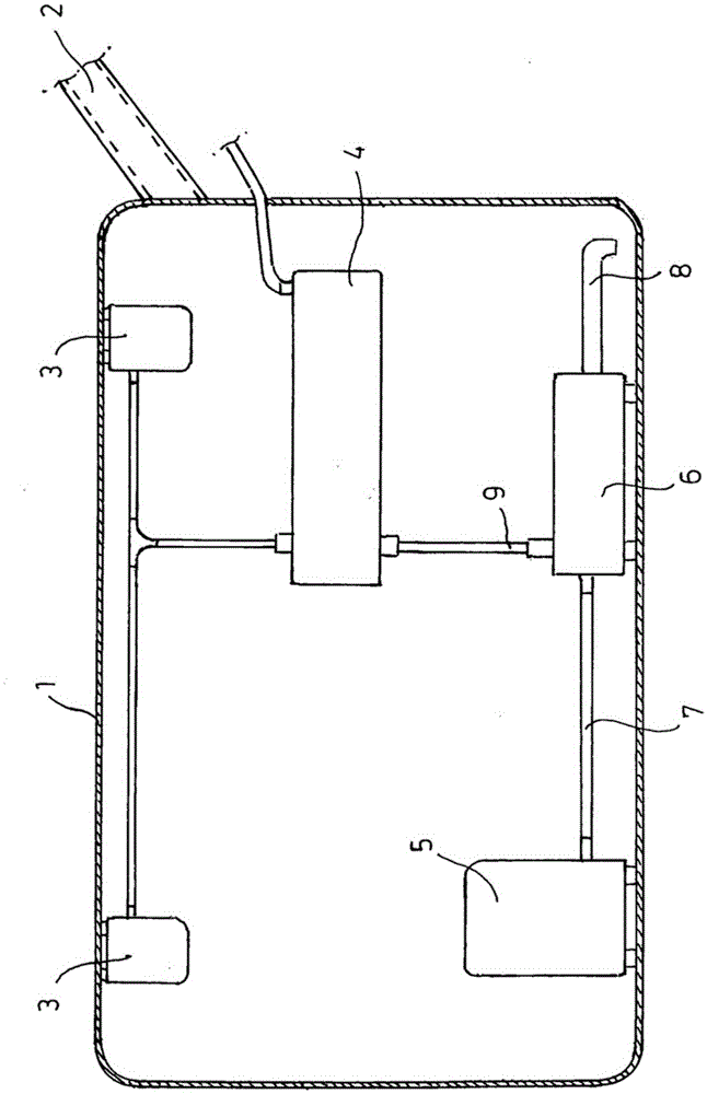
[0024] figure 1 A section of a fuel tank 1 is shown schematically, which has a cavity for receiving fuel. The fuel tank 1 includes a nozzle 2 for filling the fuel tank 1 with fuel.

[0025] The drain valve 3 is used to regulate the pressure in the fuel tank 1 , and the drain valve is arranged on the upper end of the fuel tank 1 , which is the installation position of the drain valve 3 .

[0026] The bubble extraction container 4 is used to separate fuel from fuel vapor, and the bubble extraction container is usually communicated with the surrounding environment through an activated carbon filter. Fuel accumulated in the air bubble extraction container 4 is efficiently extracted, for example, by means of a suction jet pump 11 . However, it must be ensured that no fuel enters the bubble extraction container 4 from the fuel tank 1 when the suction jet pump 11 is switched off.

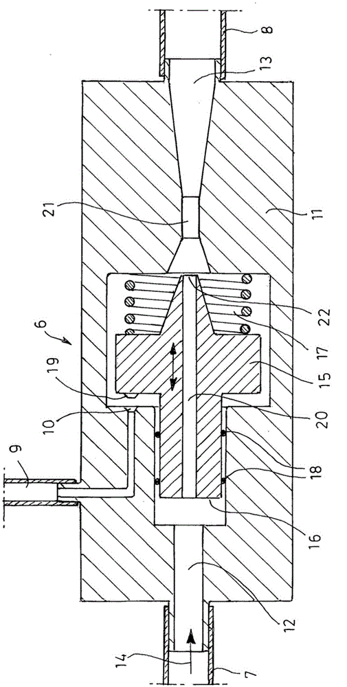
[0027] Therefore, according to the invention, the means 6 for opening the suction portion 10 as a fu...


PUM


Abstract

The invention relates to a device (6) for pressure-dependent opening of a suction portion (10), comprising a suction jet pump (11), a valve body (15) and an elastic element (17). The suction jet pump comprises a feed line (12), an output line (13) and a suction (10). A valve body is movably arranged in the feed line (12) in the delivery direction (14) of the suction jet pump (11), the valve body having an effective area influenced by the feed pressure of the suction jet pump (11) ( 16). An elastic element is arranged between the feed line (12) and the valve body (15) for exerting a force in a direction opposite to the feed pressure in the feed line (12). Among them, the effective area (16) of the valve body (15) and the elastic element (17) are designed so that the valve body (15) closes the suction part (10), so that the suction part is at a lower pressure than the supply line (12) Fluid-tight at a predetermined pressure, the suction opens when the pressure is higher than the predetermined pressure in the feed line (12).

Description

technical field [0001] The invention relates to a device for opening a suction depending on pressure. Background technique [0002] Fuel tanks used in motor vehicles today are generally produced by injection molding or blow molding of plastics, such as is disclosed in DE 10063414 A1, for example. [0003] This fuel tank includes a separation device (eg, a bubble extraction vessel) for separating fuel and fuel vapor, and the bubble extraction vessel communicates with the surrounding environment through an activated carbon filter. The role of the activated carbon filter is to equalize the pressure in the chamber when the fuel tank is refilled or when the temperature changes. When the vehicle is driven at the limit, or if a flashover occurs, a valve in the line to the activated carbon filter closes the line, preventing fuel from flowing out of the fuel tank. [0004] European patent document EP1504943B1 discloses a method of efficiently pumping out the liquid in the bubble ex...

Claims


Application Information

Patent Timeline
Patent Type & Authority Patents(China)
IPC IPC(8): B60K15/035
CPCB60K15/035F04F5/461F04F5/52
Inventor J·科伊特L·迈格雷
Owner KAUTEX TEXTRON
Learn More