Differential mechanism coupling wheel set used for urban rail vehicle

An urban track, coupled wheelset technology, applied in the directions of wheels, vehicle parts, axles, etc., can solve the problems that the vehicle cannot be automatically recovered, cannot be automatically aligned, and reduce the speed of rotation, and achieves good guiding performance and automatic alignment performance, The effect of good interchangeability

Active Publication Date: 2014-03-12
SOUTHWEST JIAOTONG UNIV
View PDF6 Cites 13 Cited by
  • Summary
  • Abstract
  • Description
  • Claims
  • Application Information

AI Technical Summary

Problems solved by technology

The problem is that the tread taper on the inner side of the wheel rim is constant, so the speed difference between the inner and outer wheels is limited
The problem is that it cannot be centered automatically when passing a straight track: when the vehicle is deflected to one side, the diameter of the rolling circle of the wheel on this side increases, but it will automatically reduce the speed of rotation, so that the forward speed of the wheel on this side is faster than that on the other side. The forward speed of the wheels on one side, that is, the vehicle cannot automatically return to the center of the track
As the vehicle will be disturbed by the outside world when it is running, it is inevitable that the wheels will not slip sideways, and once the sideways sideways are difficult to return, the wheel rim will stick to the track for a long time, resulting in wheel rail wear and noise pollution.

Method used


Image

  • Differential mechanism coupling wheel set used for urban rail vehicle
  • Differential mechanism coupling wheel set used for urban rail vehicle
  • Differential mechanism coupling wheel set used for urban rail vehicle

Examples


specific Embodiment approach

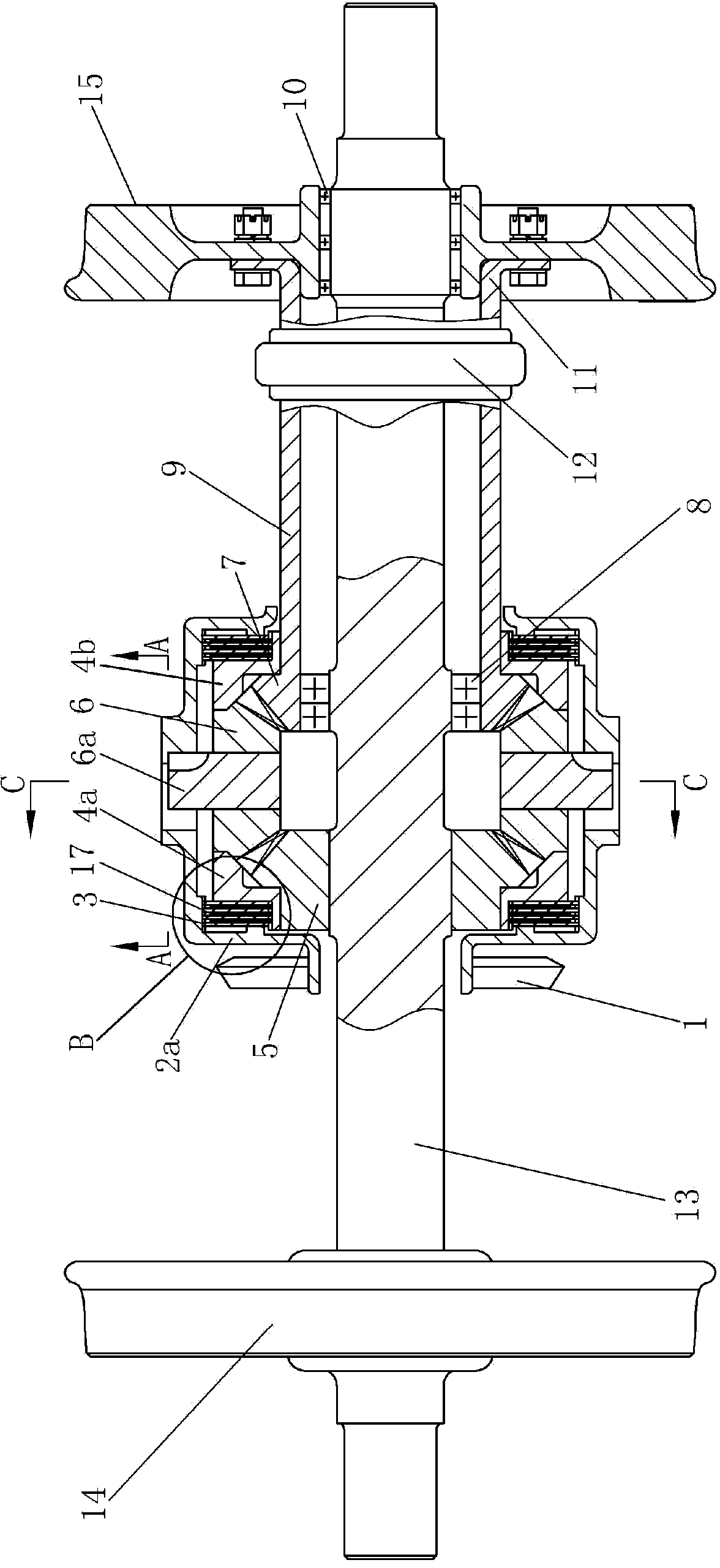
[0025] Figure 1-4 As shown, a specific embodiment of the present invention is: a differential coupling wheel set for an urban rail vehicle, including a left wheel 14 , a right wheel 15 and an axle 13 .

[0026] Left wheel 14 is fixed on the left side of axle shaft 13, and right wheel 15 is installed on the right side of axle shaft 13 by bearing 10; The specific composition of the accelerator is:

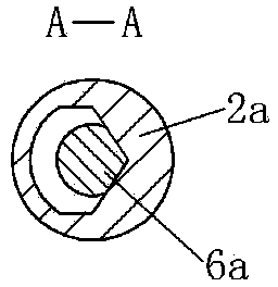
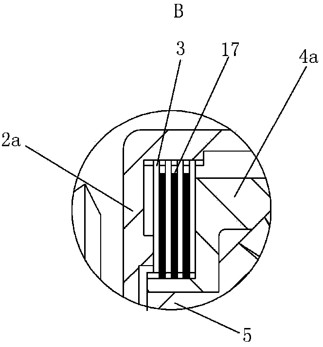
[0027] The left half-shaft sun gear 5 is fixed on the axle 13, the right half-shaft sun gear 7 is mounted on the axle 13 through the gear bearing 8, the left half-shaft sun gear 5 and the right half-shaft sun gear 7 mesh with four small planetary gears 6 ; The four planetary gears 6 are connected with the planetary shaft 6a through bearings; one side of the end section of the planetary shaft 6a is ">" shaped, and cooperates with the planetary shaft groove on the casing 2a, and the " >" shape direction is opposite; the driving gear 1 connected with the drive motor is installed on t...


PUM


Abstract

The invention discloses a differential mechanism coupling wheel set used for an urban rail vehicle. According to the coupling wheel set, an independent wheel set on the left side and an independent wheel set on the right side are coupled through a high-friction self-locking differential mechanism, and the high-friction self-locking differential mechanism is provided with a driving and driven friction plate set which can provide pre-tensioning friction torque so that the differential mechanism can be locked by itself. In a linear segment and a major radius curved segment, the different between the friction torque of a left wheel track and the friction torque of a right wheel track is smaller than the pre-tensioning friction torque of the driving and driven friction plate set, and at the moment the differential mechanism is locked, so that the left wheel and the right wheel are coupled together to rotate synchronously and have the self-guiding and self-centering capacity of traditional wheels; in a minor radius curved segment, the different between the friction torque of the left wheel track and the friction torque of the right wheel track is larger than the pre-tensioning friction torque provided by the driving and driven friction plate set, at the moment the differential mechanism is unlocked and starts a differential speed, so that the left wheel and the right wheel have different rotation speeds, and the vehicle can pass through a minor radius curve smoothly. The wheel set solves the problem of wheel track abrasion of the urban rail vehicle and the problem of passing through the minor radius curve and has the same connector as a transmission wheel set, so that interchangeability is good.

Description

technical field [0001] The invention relates to a differential coupling wheel set for rail vehicles. Background technique [0002] Urban rail transit plays an irreplaceable role in the development of modern cities because of its large capacity, safety, convenience, energy saving and environmental protection. However, in urban rail transit, since ground rail transit lines are restricted by urban buildings, small-radius curves often appear, which requires the wheelsets of urban rail vehicles to have better ability to pass through curves. [0003] The structure of the wheel set of the existing urban rail vehicles is usually that the left and right wheels are fixed on the axle, and the rotation speed of the left and right wheels is the same. Small and large conical surface, so when the vehicle deviates to one side, the radius of the rolling circle where the wheel on this side contacts the track increases, so that the forward speed of the wheel on this side is greater than that ...

Claims


Application Information

Patent Timeline
Patent Type & Authority Applications(China)
IPC IPC(8): B60B37/00B60B35/14B61C9/12
Inventor 吴兴文池茂儒杨东晓曾京邬平波戴焕云罗仁王建斌张卫华
Owner SOUTHWEST JIAOTONG UNIV
Why Eureka
Try Eureka