Reciprocating compressor

A reciprocating compressor technology, applied in the field of reciprocating compressors, can solve the problem that vibration and noise cannot be sufficiently weakened

Inactive Publication Date: 2014-03-12
LG ELECTRONICS INC
View PDF7 Cites 24 Cited by
  • Summary
  • Abstract
  • Description
  • Claims
  • Application Information

AI Technical Summary

Problems solved by technology

This will cause the vibration noise generated by the reciprocating compressor to not be sufficiently attenuated

Method used


Image

  • Reciprocating compressor
  • Reciprocating compressor
  • Reciprocating compressor

Examples


Embodiment Construction

[0050] Referring to the accompanying drawings, a number of exemplary embodiments will now be described in detail. For brevity of description with reference to the drawings, the same or equivalent components will be provided with the same reference numerals, and descriptions thereof will not be repeated.

[0051] Hereinafter, a reciprocating compressor according to the present invention will be explained in more detail with reference to the accompanying drawings.

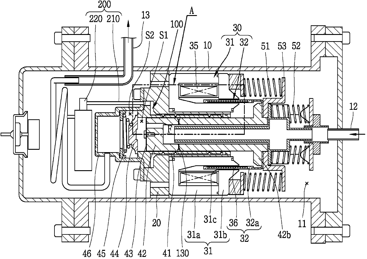
[0052] image 3 is a longitudinal sectional view of a reciprocating compressor according to the present invention.

[0053] As shown in the figure, in the reciprocating compressor according to the embodiment of the present invention, the suction pipe 12 may be connected to the inner space 11 of the casing 10, and the discharge pipe 13 may be connected to the discharge of the discharge cap 46 (to be described later). Space (S2).

[0054] The frame 20 may be installed in the inner space 11 of the cabinet 10 , and th...


PUM


Abstract

Disclosed is a reciprocating compressor. As bearing holes which constitute a fluid bearing are formed to correspond to an entire region of a piston, a frictional loss or abrasion between a cylinder and the piston can be prevented. As the bearing holes are formed at a lower part of the cylinder in a concentrated manner, the piston can be stably supported. As compression coil springs are configured as resonant springs, the cylinder and the piston can be easily aligned with each other in a concentric manner, and performance of the reciprocating compressor can be enhanced. As gas through holes are formed at the piston in a radial direction, a pressure of a bearing space can be lowered and thus a refrigerant can be smoothly introduced into the bearing space through a gas pocket. As a shell has a double structure of an outer shell and an inner shell, vibrations generated from the reciprocating compressor can be attenuated by friction occurring between the outer shell and the inner shell. As a casing has a double structure of an outer shell and an inner shell, vibration noise generated from the reciprocating compressor can be attenuated.

Description

technical field [0001] This invention relates to reciprocating compressors, and more particularly to reciprocating compressors having fluid bearings. Background technique [0002] In general, a reciprocating compressor draws in refrigerant, compresses it, and discharges it as a piston performs linear reciprocating motion within a cylinder. According to the driving method of the piston, the reciprocating compressor can be classified into a connection type and a vibration type. [0003] In the connection type reciprocating compressor, refrigerant is compressed as a piston performs reciprocating motion within a cylinder in a state where a rotating shaft of a rotary electric machine is connected to a connecting rod. On the other hand, in the vibration type reciprocating compressor, in a connected state of a mover connected to a reciprocating motor, refrigerant is compressed as a piston vibrates while performing reciprocating motion within a cylinder. The present invention rela...

Claims


Application Information

Patent Timeline
IPC IPC(8): F04B39/12
CPCF04B39/0276F04B39/0005F01B1/00F04B35/045F04B39/12F04B53/18F04B39/122F04B39/121F04B35/04F04B39/123
Inventor 安光运崔基喆金烔汉奇成铉朴景培
Owner LG ELECTRONICS INC
Why Eureka
Try Eureka