Decelerator with output pinion of wind power generation system

A technology of wind power generation system and deceleration device, which is applied in the direction of wind power generator components, wind power generation, wind power engine, etc., which can solve problems such as difficult and high load capacity, and achieve the effect of improving the supporting capacity

Inactive Publication Date: 2010-10-06
SUMITOMO HEAVY IND LTD
View PDF7 Cites 6 Cited by
  • Summary
  • Abstract
  • Description
  • Claims
  • Application Information

AI Technical Summary

Problems solved by technology

Therefore, it is particularly difficult to support the side of the output shaft opposite to the drive source side with high load capacity and high strength.

Method used


Image

  • Decelerator with output pinion of wind power generation system
  • Decelerator with output pinion of wind power generation system
  • Decelerator with output pinion of wind power generation system

Examples


Embodiment Construction

[0027] Hereinafter, a reduction gear transmission with an output pinion of a wind power generation system according to an example of an embodiment of the present invention will be described in detail.

[0028] Figure 7 is a brief front view of the wind power generation system 10, Figure 8 is a side view of the wind power generation system 10 .

[0029] This wind power generation system 10 includes a power generation unit (pod) 12 on the uppermost portion of a cylindrical support 11 . Figure 9 It is a schematic perspective view showing the power generation unit 12 . A driving device 14 for driving a yaw (Yaw) and a driving device 16 for driving a pitch (Pitch) are incorporated in the power generating unit 12 . The driving device 14 for yaw driving controls the rotation angle of the entire power generating unit 12 , while the driving device 16 for pitch driving controls the pitch angles of the three wind turbine blades 20 attached to the nose cone 18 .

[0030] In this em...


PUM


Abstract

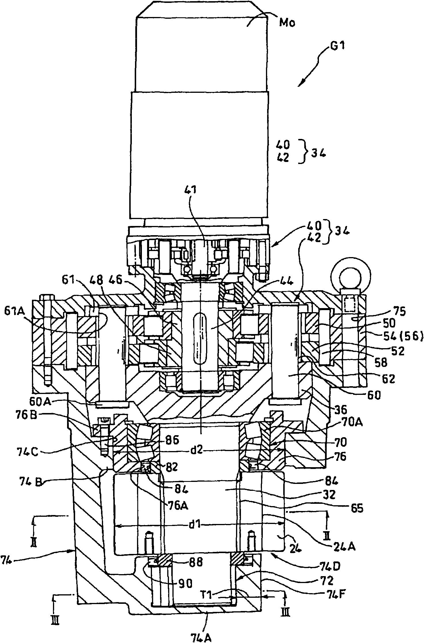
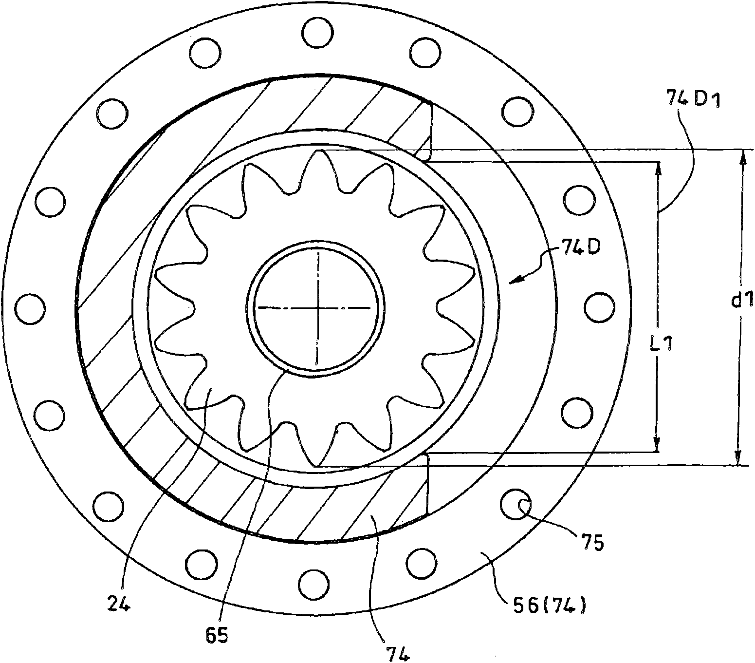
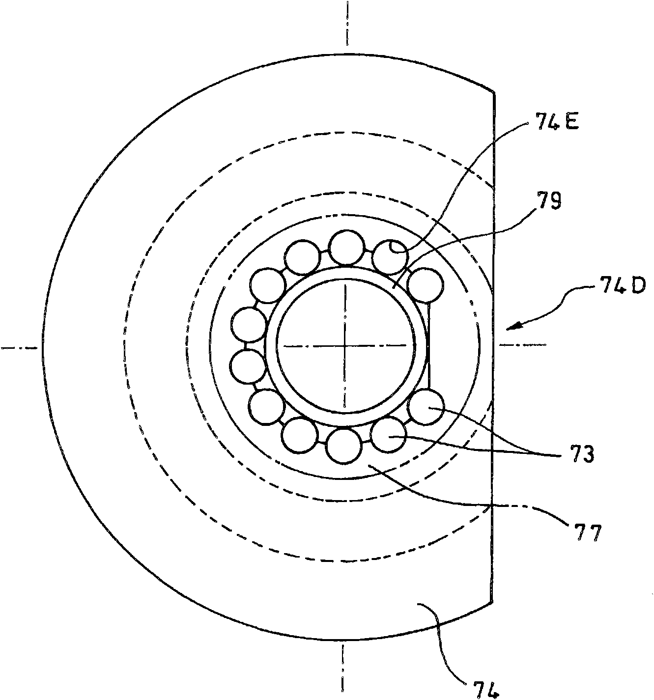
The invention provides a decelerator with an output pinion of a wind power generation system, which especially improves the bearing capability of the output shaft on one side opposite to the drive source side when dually supporting the output shaft of the decelerator with the output pinion of the wind power generation system. In the decelerator (G1) with the output pinion of the wind power generation system, the output shaft (32) is dually supported by a pair of bearings including an automatic aligning roller bearing (70) and a roller bearing (72); in the pair of bearings (70, 72), the roller (73) on one side opposite to the drive source side is composed of a plurality of rollers not only doing rotation but also doing revolution; and there has no roller (73) on the engaged window (74D) side.

Description

technical field [0001] This application claims priority based on Japanese Patent Application No. 2009-81711 filed on March 30, 2009. All the content of the application is used in this specification by reference. [0002] The invention relates to a reduction gear with an output pinion for a wind power generation system. Background technique [0003] Patent Document 1 discloses a "reduction gear unit with an output pinion" used for rotational driving of a power generation unit (pod) or the like of a wind power generation system. The reduction gear with output pinion includes: a reduction mechanism for reducing the rotation of the electric motor; an output shaft connected to or integrated with an output member of the reduction mechanism; and an output pinion provided on the output shaft. A reduction gear with an output pinion is installed on the side of the power generation unit, and the output pinion meshes with a rotating internal gear fixed on the side of the pillar of the...

Claims


Application Information

Patent Timeline
Patent Type & Authority Applications(China)
IPC IPC(8): F03D11/00
CPCY02E10/723Y02E10/722Y02E10/72Y02E60/10
Inventor 峰岸清次
Owner SUMITOMO HEAVY IND LTD
Why Eureka
Try Eureka