
Roller bearing nut screw pair

A roller and screw technology, applied in belts/chains/gears, mechanical equipment, transmission devices, etc., can solve the problems such as insufficient positioning accuracy of nut-screw pair, large frictional resistance, complex processing technology, etc. Insufficient length of processing equipment, reduced friction loss, and high transmission efficiency

Active Publication Date: 2015-12-30
洪荣华
View PDF8 Cites 0 Cited by
  • Summary
  • Abstract
  • Description
  • Claims
  • Application Information

AI Technical Summary

Problems solved by technology

[0002] In the prior art, Acme screw and ball screw are mainly used in the commonly used nut and screw pairs: In the traditional Acme screw, the outside of the screw and the inside of the nut have a thread structure that matches each other, and the screw and the nut pass through the thread structure. The surface contact between them performs sliding frictional movement, although the load it carries is large, the frictional resistance is also large, easy to wear, and the service life is short; in the ball screw, balls are arranged in the thread structure outside the screw and inside the nut, and the steel ball is connected with the screw and the nut. Nut point contact for rolling friction movement, although the friction force is reduced and the movement is flexible, but the manufacturing cost is high, the two ends cannot carry large loads, and generally cannot be self-locking
[0003] Chinese Patent No. 200680022055.6 discloses a patent titled "Roller Screw and Its Manufacturing Method". In this patent, more than two raceways are formed between the threaded shaft (ie, screw) and the nut, and the two raceways have different directions. There are multiple rollers, and there are multiple circulation members with no load return circuit, so that the ball screw can load the load in two directions of the axis of the threaded shaft; but the structure of the ball screw is complicated, the processing technology is complicated, and it is not well overcome. The defect that the nut screw pair in the prior art cannot bear large loads
[0004] Chinese Patent No. 92224740.4 discloses a patent named "Roller Screw Pair". In this patent, the nut body is provided with a radial garden hole, and a cylindrical roller is provided to pass through the radial garden hole on the nut and snap into it. The tooth socket of the screw can bear large loads, is convenient for assembly and positioning, and is equipped with needle bearings for smooth rolling; however, the arrangement of the radial holes and cylindrical rollers of the roller screw pair is not clear, and There is no solution proposed to overcome the defect of insufficient positioning accuracy of the nut and screw pairs in the prior art

Method used


Image

  • Roller bearing nut screw pair
  • Roller bearing nut screw pair
  • Roller bearing nut screw pair

Examples


Embodiment Construction

[0045] The present invention will be further described below in conjunction with the accompanying drawings and examples.

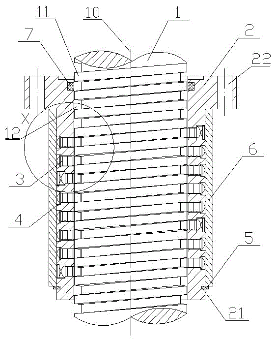
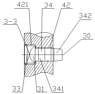
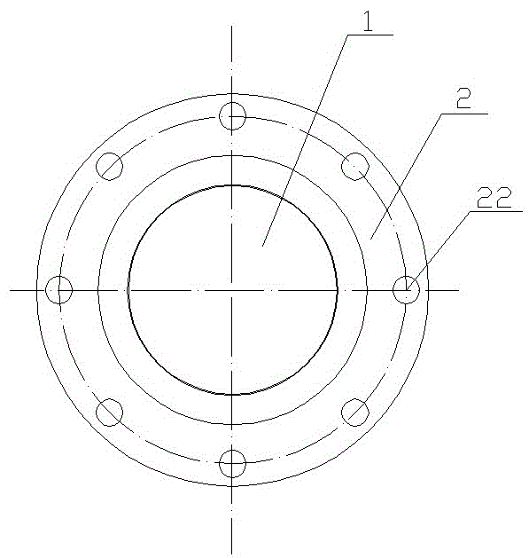
[0046] see Figure 1-Figure 16 , This embodiment includes a screw 1, a nut 2, a roller 3, a roller hole 4, a circlip 5, an outer ring 6 and a dustproof device 7.

[0047] In this embodiment, the center of the nut 2 has a circular through hole and the inner wall of the nut 2 has no internal thread, and the cylindrical screw 1 penetrates into the nut 2; the screw 1 has an external thread, and the concave part of the external thread is a tooth The groove 11 and the protruding part are the tooth body 12. The maximum outer diameter D of the screw rod 1 (that is, the outer diameter of the top of the tooth body 12) is slightly smaller than the inner diameter of the nut 2. The tooth groove 11 forms a spiral track as a whole, and the tooth groove 11 and the tooth body 12 section (such as figure 1 shown) are isosceles trapezoidal, and the tooth profile angle α is ...


PUM


Abstract

The invention relates to a pin roller bearing nut and screw rod pair. The pin roller bearing nut and screw rod pair comprises a screw rod and a nut, wherein the screw rod is externally provided with an outer thread; the pin roller bearing nut and screw rod pair further comprises a pin roller; the pin roller comprises a pin roller body; a roller head part of the pin roller body is in a cone frustum structure; a roller main body of the pin roller body is in a cylindrical structure; the nut is provided with pin roller holes; the roller main body is located in the pin roller holes to form clearance fit; the roller head part is located in a tooth groove of the screw rod to form the clearance fit; the diameter of each pin roller hole is a half of a screw pitch of the screw rod and the pin roller hole is arranged spirally; at least two circles of the pin roller holes are arranged; the pin roller holes are divided into pin roller positioning holes and pin roller adjusting holes; the pin roller positioning holes and the pin roller adjusting holes are arranged on a spiral track at intervals; the centers of the pin roller positioning holes are located on the central line of the spiral track; the centers of the pin roller adjusting holes are upwards or downwards deviated for the distance of one tolerance clearance relative to the axial direction of the central line of the spiral track. The pin roller bearing nut and screw rod pair is high in positioning precision, is great in bearing load, is safe and reliable in performance, is reasonable in structure, is convenient to mount and maintain and is wide in applicable range.

Description

technical field [0001] The invention relates to a nut screw pair, in particular to a roller bearing nut screw pair, which is mainly used in machines with large bearing capacity and high positioning accuracy. Background technique [0002] In the prior art, Acme screw and ball screw are mainly used in the commonly used nut and screw pairs: In the traditional Acme screw, the outside of the screw and the inside of the nut have a thread structure that matches each other, and the screw and the nut pass through the thread structure. The surface contact between them performs sliding frictional movement, although the load it carries is large, the frictional resistance is also large, easy to wear, and the service life is short; in the ball screw, balls are arranged in the thread structure outside the screw and inside the nut, and the steel ball is connected with the screw and the nut. Nut point contact for rolling friction movement, although the friction force is reduced and the movem...

Claims


Application Information

Patent Timeline
Patent Type & Authority Patents(China)
IPC IPC(8): F16H25/22
CPCF16H25/22F16H25/2261
Inventor 洪荣华洪泽斌
Owner 洪荣华
Learn More