
Fast pneumatic valve

A pneumatic valve, fast technology, applied in valve details, valve devices, engine components, etc., can solve the problems of poor low-speed performance of air cannons, unguaranteed air cannon accuracy, increased design pressure, etc., to achieve smooth motion and improve stress. , the effect of improving the low speed capability

Active Publication Date: 2014-03-12
CHINA AIRPLANT STRENGTH RES INST
View PDF9 Cites 10 Cited by
  • Summary
  • Abstract
  • Description
  • Claims
  • Application Information

AI Technical Summary

Problems solved by technology

[0006] The response speed of the cone valve is related to the working pressure of the main air chamber. The response is fast at high pressure and slow at low pressure. This is also the main reason why the low-speed performance of the air cannon using this type of pneumatic valve is not good;
[0007] Because the response speed of the cone valve and the time to fully open are related to the working pressure, the accuracy of the air cannon cannot be guaranteed;
[0008] In order to ensure a reliable seal between the cone valve and the gun barrel, when the working pressure of the main air chamber increases, the pressure of the air chamber 1 must also increase, which will increase the design pressure of the system and increase the cost

Method used


Image

  • Fast pneumatic valve

Examples


Embodiment Construction

[0017] Below in conjunction with embodiment and accompanying drawing, the present invention is further described:

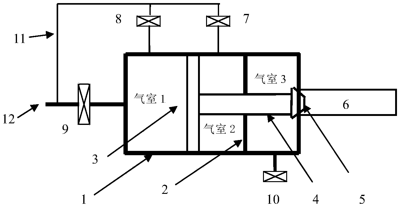
[0018] see figure 1 , which is a structural schematic diagram of the fast pneumatic valve of the present invention. The fast pneumatic valve includes a valve body, a cone valve, a solenoid valve, a partition, and a gun barrel. Among them, the cone valve and the partition are arranged in the valve body, the piston of the cone valve and the valve body are separated from the air chamber 1 (the first air chamber), the valve head of the cone valve passes through the partition and can cooperate with the nozzle of the gun barrel, the cone valve The space between the diaphragm and the valve body is the air chamber 2 (the second air chamber), the space between the diaphragm and the valve body is the air chamber 3 (the third air chamber), and the air chamber 1 communicates with the outside atmosphere, and the air chamber 3 Connects to the main chamber for firing the barr...


PUM


Abstract

The invention belongs to an air path control technology, and particularly relates to a fast pneumatic valve applied to air path control. The fast pneumatic valve comprises a valve body, a cone valve, electromagnetic valves, a separation plate and a gun barrel, wherein the cone valve and the separation plate are arranged in the valve body, a first air chamber is separated by a piston of the cone valve and the valve body, a valve head of the cone valve passes through the separation plate and can be matched with an opening of the gun barrel, a space among the cone valve, the separation plate and the valve body is a second air chamber, a third air chamber is formed between the separation plate and the valve body, in addition, the first air chamber is communicated with external atmosphere, and the third air chamber is communicated with a main air chamber used for emitting the gun barrel. Meanwhile, each air chamber is respectively provided with the electromagnetic valves used for controlling the air path closing. The fast pneumatic valve has the advantages that the cone valve movement is irrelevant to the work pressure, so the repeatability of the fast pneumatic valve is better, the speed precision of an air cannon device can be effectively improved, the piston lifting movement is smoother, the clamping cannot easily occur, and the low-speed capability of the air cannon device can be effectively improved.

Description

technical field [0001] The invention belongs to the gas path control technology, in particular to a fast pneumatic valve applied to the gas path control. Background technique [0002] In the impact dynamics experiments of structures and materials, low-velocity air cannon is a commonly used test device, and its launch control device is its core component. Generally, pneumatic valves or diaphragms are used for control, and pneumatic valves are reliable and repeatable because of their reliable action. , Fast response and wider application. [0003] At present, the schematic diagram of the pneumatic valve used in the air cannon device which is widely used in China is shown in figure 1 , its working principle is to inflate the air chamber 1, so that the cone valve moves to the right to isolate the barrel from the main air chamber; the main air chamber is inflated, and at this time, the air chamber 2 is connected with the main air chamber, and the pressure is consistent with the ...

Claims


Application Information

Patent Timeline
Patent Type & Authority Applications(China)
IPC IPC(8): F16K31/122F16K31/06
CPCF16K31/122
Inventor 刘小川
Owner CHINA AIRPLANT STRENGTH RES INST
Learn More