Composite pipe hydraulic expansion method, manufacturing device and obtained composite pipe

A composite pipe and hydraulic technology, applied in the field of composite pipes, can solve problems such as inconvenience in processing, and achieve the effects of short filling time, high efficiency, and preventing seal failure.

Active Publication Date: 2014-03-12
QINGDAO ZHONGRUITAI MESNAC TECH CO LTD
View PDF7 Cites 6 Cited by
  • Summary
  • Abstract
  • Description
  • Claims
  • Application Information

AI Technical Summary

Problems solved by technology

The pipe ends of the composite pipes used in many industries (such as: petroleum) have external threads. The process requires processing the external threads on the outer pipes before expansion. The existence of composite blind spots at the pipe ends also brings inconvenience to subsequent processing.

Method used


Image

  • Composite pipe hydraulic expansion method, manufacturing device and obtained composite pipe
  • Composite pipe hydraulic expansion method, manufacturing device and obtained composite pipe
  • Composite pipe hydraulic expansion method, manufacturing device and obtained composite pipe

Examples


Embodiment 1

[0072] image 3 It is an embodiment of the present invention and is suitable for use when the compounded pipe is relatively short.

[0073] The plug 4 is an integral rod body, and sealing rings 5 ​​are installed at both ends. The plug 4 is provided with passages communicating with the inner ring of the sealing ring 5 and the inner cavity of the inner pipe 2 respectively, and the passage connected with the inner ring of the sealing ring 5 passes through A The liquid is introduced through the mouth of the inner tube 3, and the channel connected with the inner cavity of the inner tube 3 is introduced into the liquid through the B port; the outer tube 2 and the inner tube 3 that need to be bulged are first set together; then the collar 1 is installed close to the two ends of the outer tube 2 and fixed, the inner diameter of the collar 1 is equal to the inner diameter of the outer tube 2; then the plug 4 with the sealing ring 5 installed is inserted into the inner hole of the inner...

Embodiment 2

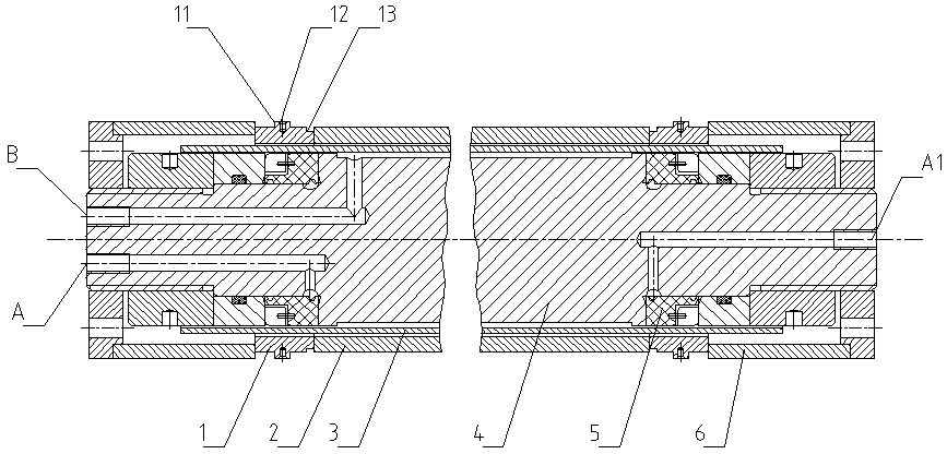
[0081] Figure 4 It is another embodiment of the present invention, and is suitable for use when the expanded tube is relatively long.

[0082] In this embodiment, the plug 4 is a split type, the left plug is fixed, and the right plug is movable, which are respectively installed on both sides of the equipment. For the convenience of comparison, the upper part is the initial state of swelling, and the lower part is Closed state.

[0083]During expansion, the left side plug 4 is fixed, the A port connected to the inner ring of the sealing ring is drawn out on the side, and the B port connected to the inner tube cavity is drawn out in the center; the right side plug is flexibly connected to the sealing seat 7, and connected to the inner The A1 port of the ring is drawn out on the side, and the B1 port connecting the inner tube cavity communicates with the cavity 71 on the sealing seat 7, and communicates with the outside world through the B2 port arranged on the sealing seat 7. ...

Embodiment 3

[0093] Figure 5 It is an embodiment when the plugs of the present invention are all flexibly connected. The plugs on both sides are movable, so the effect is more obvious. The upper part is the final state of bulging, and the lower part is the initial state of bulging.

[0094] This example is Figure 4 The improvement of the embodiment is different in that a positioning structure matching the outer pipe is provided on the plugs 4 on both sides.

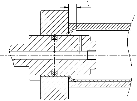
[0095] The plug 4 is provided with a stepped boss 41 that matches the outer tube 2. The inner diameter of the stepped boss 41 is larger than the inner diameter of the inner tube 3 and smaller than the inner diameter of the outer tube 2. When expanding, the longer one end of the stepped boss is shortened. The end surface of the platform 41 first touches the end surface of the collar 1 to determine the position of the end of the inner tube 2, and the subsequent deformation of the inner tube 3 is based on this, finally making the pos...


PUM


Abstract

The invention provides a composite pipe hydraulic expansion method, which comprises the following steps that (1) a plug provided with a sealing ring in the circumferential direction is inserted into an inner pipe; (2) sealing pressure liquid is introduced to a position between the plug and an inner ring of the sealing ring for sealing the end part of the inner pipe; (3) the expansion is carried out, before the expansion, a sleeve ring with the same inner diameter as an outer pipe of a composite pipe is arranged in a way of tightly pasting the end surface of the outer pipe of the composite pipe requiring the expansion, and in addition, the innermost end of the sealing ring is arranged outside the end surface of the outer pipe of the composite pipe. The sealing position exceeds the end surface of the outer pipe, so the pressure inside an inner pipe cavity can reach the end part of the outer pipe, and the combining quality is ensured. The defect of composite blind region reservation at the end part of the composite pipe manufactured in the prior art is overcome, and the composite pipe can be used without cutting off the blind region, so the cost is reduced in aspects of both materials and the process. The cutting is not needed, so great convenience is brought for the subsequent processing of external screw threads formed at the pip end of the composite pipe before the expansion.

Description

technical field [0001] The invention relates to the technical field of composite pipe hydroforming, in particular to a composite pipe hydraulic expansion method and manufacturing device and a composite pipe obtained according to the method. Background technique [0002] The composite pipe composed of multi-layer materials can exert the properties of different materials and is cost-effective. It is widely used in petroleum, chemical, pharmaceutical and food processing industries. The composite pipe produced by the hydraulic expansion method has uniform expansion force and can be calculated, and there is no scratch or damage on the inner wall surface of the composite pipe, and there is no work hardening phenomenon. [0003] "Research on the Principle and Technology of Multilayer Composite Pipe Hydraulic Jointing" (Harbin Institute of Technology, 2010 master's degree thesis, page 65) discloses a composite pipe hydraulic "expansion joint experimental device", "adding a The seal...

Claims


Application Information

Patent Timeline
Patent Type & Authority Applications(China)
IPC IPC(8): F16L9/00F16L55/10
CPCB21D26/033B21D26/045F16L55/10
Inventor 王中华吕冰段英良邹建亭
Owner QINGDAO ZHONGRUITAI MESNAC TECH CO LTD
Why Eureka
Try Eureka