
Monitoring system based on EtherCAT network

A monitoring system and network technology, applied in the field of communication, can solve the problems of too many wire harnesses, strong fieldbus special type, lack of special type, etc., and achieve the effect of flexible network topology, high effective data rate and simple system configuration.

Inactive Publication Date: 2014-03-12
SHANGHAI JIAO TONG UNIV
View PDF2 Cites 28 Cited by
  • Summary
  • Abstract
  • Description
  • Claims
  • Application Information

AI Technical Summary

Problems solved by technology

[0003] The traditional monitoring system has communication technologies such as Ethernet transmission and field bus control. Among them, Ethernet has certain advantages in bandwidth and speed but lacks real-time performance. Therefore, field bus is used to realize mechanism control. To meet the real-time requirements, but the field bus has certain limitations on the transmission rate
On the other hand, the number of sold components of the field bus is very small, and the special type of the field bus is strong, and the protocol conversion between different buses is complicated, so the comprehensive cost of the control system and field devices is quite high
Furthermore, in this traditional solution, there are many wiring harnesses, and the wiring cost is particularly significant.
At the same time, flexibility in terms of signal granularity has traditionally been achieved through modular field devices operating in subordinate subnetworks, which add to the overall complexity of the system and have significant disadvantages in terms of real-time and cycle times

Method used


Image

  • Monitoring system based on EtherCAT network
  • Monitoring system based on EtherCAT network
  • Monitoring system based on EtherCAT network

Examples


Embodiment Construction

[0030] The following is a detailed description of the embodiments of the present invention: this embodiment is implemented on the premise of the technical solution of the present invention, and provides detailed implementation methods and specific operation processes. It should be noted that those skilled in the art can make several modifications and improvements without departing from the concept of the present invention, and these all belong to the protection scope of the present invention.

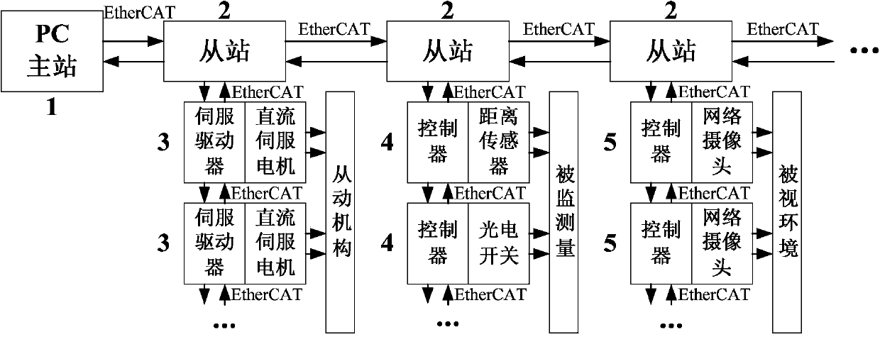
[0031] Please also see Figure 1 to Figure 3 .

[0032] The present embodiment provides a kind of monitoring system based on EtherCAT network, comprises following parts:

[0033] - a master station and a plurality of slave stations supporting the EtherCAT protocol, the master station and the plurality of slave stations are connected in series to form a network segment, and the master station is located at one end of the network segment;

[0034] -Servo control module supporting EtherC...


PUM


Abstract

The invention discloses a monitoring system based on an EtherCAT network. The monitoring system comprises the following components including a main station, a plurality of sub stations, a servo control module, a sensing signal module and an image collecting module, wherein the main station and the sub stations support EtherCAT protocols, the main station and the sub stations are connected in series for forming a network segment, the main station is positioned at one end of the network segment, the server control module supports the EtherCAT protocols, the sensing signal module supports the EtherCAT protocols, the image collecting module supports the EtherCAT protocols, each sub station is respectively connected with the corresponding servo control module, the sensing signal module and the image collecting module in series for forming a sub network segment. The monitoring system provided by the invention realizes the monitoring on the seen environment and the remote control operation on an execution mechanism under the long-distance condition, each module part forming the monitoring system respectively supports the EtherCAT protocols, and the monitoring system has the advantages that the network topology structure is flexible, the system configuration is simple, the communication speed is high, the real-time performance is good, the effective data rate is high, and the like.

Description

technical field [0001] The invention relates to a monitoring system in the technical field of communication, in particular to a monitoring system based on an EtherCAT network. Background technique [0002] In the monitoring system, the main task is to perform some necessary control operations on the actuator according to the remote real-time scene and status information feedback. Because there is a certain spatial distance between the control unit and the actuator, it makes Control instructions, feedback information, etc. need to be transmitted through communication methods suitable for long-distance situations. [0003] The traditional monitoring system has communication technologies such as Ethernet transmission and field bus control. Among them, Ethernet has certain advantages in bandwidth and speed but lacks real-time performance. Therefore, field bus is used to realize mechanism control. To meet the real-time requirements, and the field bus has certain limitations in t...

Claims


Application Information

Patent Timeline
IPC IPC(8): G05B19/048G05B19/418
Inventor 唐厚君陆亭华曹其新董诗阳蔡位焜
Owner SHANGHAI JIAO TONG UNIV
Learn More