Eureka AIR delivers breakthrough ideas for toughest innovation challenges, trusted by R&D personnel around the world.

Method and system for constructing electromagnetic hotspot distribution diagram of target

A distribution map, electromagnetic technology, applied in the field of radar, can solve the problems of consistent scattering intensity, strong electromagnetic scattering structure error, stealth design defects and other problems

Active Publication Date: 2014-03-12
BEIJING INST OF ENVIRONMENTAL FEATURES
View PDF1 Cites 4 Cited by
  • Summary
  • Abstract
  • Description
  • Claims
  • Application Information

AI Technical Summary

Problems solved by technology

[0006] The inventors of the present invention have found that although the above-mentioned method can determine the distribution of the target surface circuit, in some cases, the intensity of the target surface current does not coincide with the target surface scattering intensity, that is, by relying on the current distribution There will be certain errors in judging the strong electromagnetic scattering structure of the target model, which makes the stealth design for the target flawed

Method used


Image

  • Method and system for constructing electromagnetic hotspot distribution diagram of target
  • Method and system for constructing electromagnetic hotspot distribution diagram of target
  • Method and system for constructing electromagnetic hotspot distribution diagram of target

Examples


Embodiment Construction

[0052] In order to make the objectives, technical solutions, and advantages of the present invention clearer and more comprehensible, the present invention will be further described in detail below with reference to the accompanying drawings and preferred embodiments. However, it should be noted that many details listed in the specification are only to enable the reader to have a thorough understanding of one or more aspects of the present invention, and these aspects of the present invention can be implemented even without these specific details.

[0053] The terms "module" and "system" used in this application are intended to include computer-related entities, such as but not limited to hardware, firmware, a combination of software and hardware, software, or software in execution. For example, a module may be, but is not limited to: a process, a processor, an object, an executable program, a thread of execution, a program, and / or a computer running on the processor. For example...


PUM


Abstract

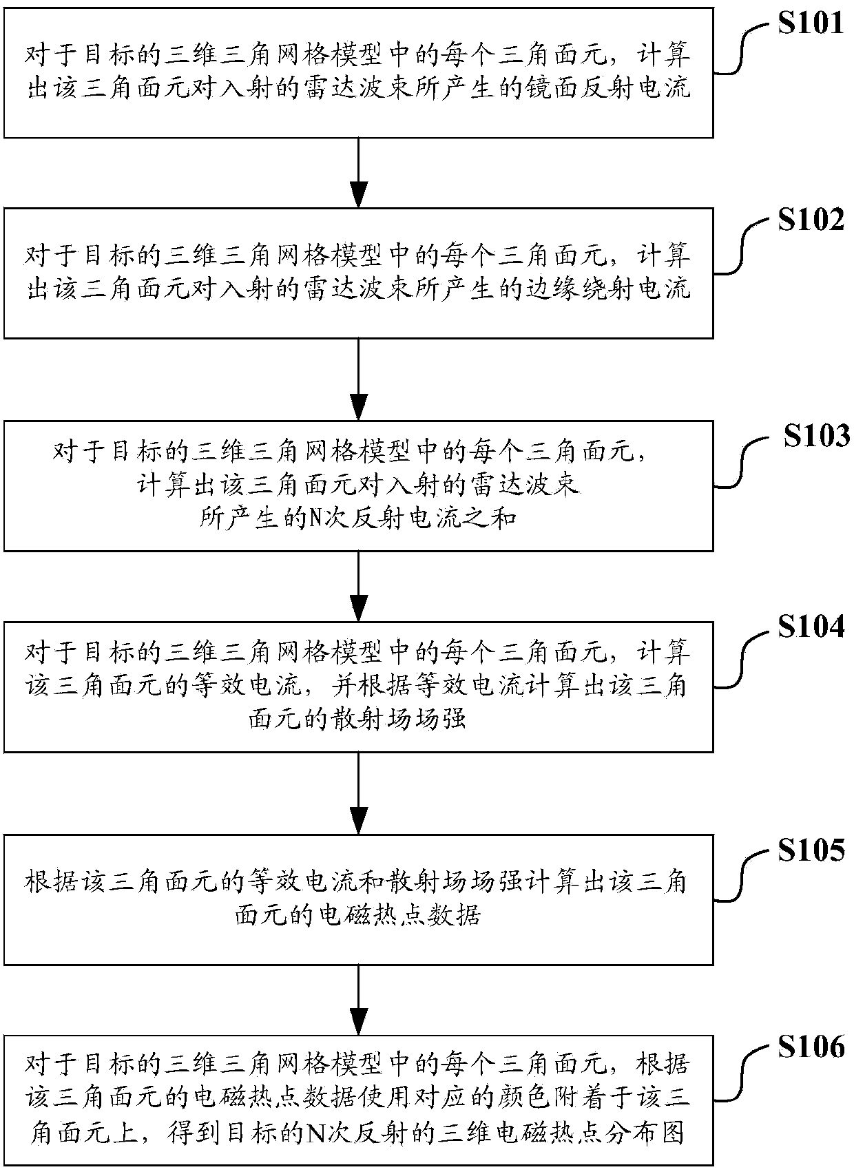
The invention discloses a method and system for constructing an electromagnetic hotspot distribution diagram of a target. The method includes the steps that mirror reflection currents, edge diffraction currents and the sum of N reflected currents, generated on incident radar beams, by each triangular surface element in a three-dimensional triangular mesh model of the target are calculated according to the incident direction of the appointed radar beams, so that the equivalent currents of the triangular surface element are obtained; after the scattering electric field intensity of each triangular surface element is calculated according to the equivalent currents of the triangular surface element, and electromagnetic hotspot data of the triangular surface element are calculated according to the equivalent currents and scattering electric field intensity of the triangular surface element; the electromagnetic hotspot data of each triangular surface element in the three-dimensional triangular mesh mode are attached to the triangular surface element through corresponding colors, so that the three-dimensional electromagnetic hotspot distribution diagram of N times of reflection of the target is obtained; N is a preset natural number. The method and system are applied to accurately judging the strong electromagnetic scattering structure of the target.

Description

Technical field [0001] The invention relates to radar technology, in particular to a method and system for constructing a target electromagnetic hotspot distribution map. Background technique [0002] Stealth technology is the general term for various technologies that study how to reduce the possibility of targets being discovered and tracked by detection systems such as electromagnetic waves, acoustic waves, infrared light and visible light. Among them, radar stealth technology for electromagnetic waves is the focus. The core of radar stealth technology is to reduce RCS (Radar Cross Section). Generally, in the stealth design of radar scattering targets, it is necessary to analyze the radar scattering characteristics of the target model first, and judge the target model based on the analysis data. Strong electromagnetic scattering structure, and then take various RCS reduction measures for these strong electromagnetic scattering structure parts. [0003] At present, the method of...

Claims


Application Information

Patent Timeline
IPC IPC(8): G06F19/00
Inventor 李焕敏闫华董纯柱王超殷红成
Owner BEIJING INST OF ENVIRONMENTAL FEATURES
Why Eureka
Eureka Blog
Learn More