Parallel Packet Routing Detection Method

A detection method and message technology, applied in digital transmission systems, electrical components, transmission systems, etc., can solve the problems of inability to detect the packet loss rate of intermediate nodes and low efficiency, and achieve parallel routing detection, low efficiency, and faster detection efficiency effect

Inactive Publication Date: 2016-08-31
SOUTHEAST UNIV
View PDF3 Cites 0 Cited by
  • Summary
  • Abstract
  • Description
  • Claims
  • Application Information

AI Technical Summary

Problems solved by technology

This method needs to detect each intermediate node in order when detecting a target node, which takes a long time to detect and is inefficient
At the same time, this method only detects the IP address of the intermediate routing node, but cannot detect the performance indicators such as the packet loss rate of the intermediate node.

Method used


Image

  • Parallel Packet Routing Detection Method
  • Parallel Packet Routing Detection Method

Examples


Embodiment 1

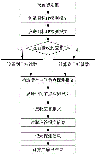
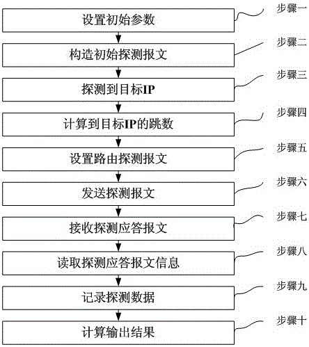
[0026] A parallel message routing detection method, characterized in that:

[0027] Step 1: Set a detected IP address A, set the number k of each type of message sent, k=1~100, set an array structure D including 32*k records, each record of the array structure D includes The TTL number of the sent message, the time stamp of the sent message, the time stamp of the received response message, the identification number of the sent message and the source IP address of the response message, enter step 2;

[0028] Step 2: an ICMP message with detected IP address A as the target address is set, the TTL field of the IP message header of the ICMP message is set to 64, and the ICMP message is sent by the measurement point to the target address, Go to step three;

[0029] Step 3: If the response message of the ICMP message is received, then measure the value TL of the TTL field of the IP header in the received response message, and enter step 4; if the response message is not received, s...

Embodiment 2

[0038] A parallel message routing detection method, characterized in that:

[0039] Step 1: The IP address of the measurement point is 101.4.116.222, set a detected IP address 121.194.0.239, set the number k of each type of message sent, k=3, and set an array structure including 32*k records D, each record of the array structure D includes the TTL number of the sent message, the timestamp of the sent message, the timestamp of the received response message, the identification number of the sent message and the source IP address of the response message, and enter step 2 ;

[0040] Step 2: set an ICMP message with the detected IP address 121.194.0.239 as the target address, the TTL field of the IP message header of the ICMP message is set to 64, and the ICMP message is sent to the target address by the measurement point text, go to step 3;

[0041] Step 3: after receiving the response message of the ICMP message, measure the value TL of the IP header TTL field in the received r...


PUM


Abstract

A parallel message route detection method, an ICMP message with the detected IP address A as the target address is set, if the response message of the ICMP message is received, the number of hops n from the measurement point to the target node is calculated , otherwise set the number of hops to 32, set n types of ICMP messages of the same target node A, and set the TTL field of each ICMP message to n different positive integers from 1 to n, from the measurement point to The target address sends the set n types of ICMP messages, k ICMP messages of each type are sent, and the sending timestamp, identification number and TTL of each message are recorded, and the response messages of all ICMP messages are received and Mark the receiving time stamp, record the time stamp of the response message and the IP address of the response in the record where the identification number of the sent message in the array is the same as the identification number of the original IP message header in the response message measured, and calculate the output to reach the target node Routing, delay and packet loss rate of intermediate nodes.

Description

technical field [0001] The technology relates to the technical field of network measurement, in particular to a parallel message routing detection method. Background technique [0002] The basic principle of route detection is to send ICMP messages with different time-to-live (TTL) values ​​to the target address. Each router on the path will decrement the TTL on the message by 1 before forwarding the message. When the TTL on the message decreases When it is 0, the router sends the "ICMP timeout" message back to the source address, and the ICMP message includes the information of the intermediate router. According to this principle, you can first send a response packet with a TTL of 1 to the target address, and increase the TTL by 1 in each subsequent sending process until the target response or TTL reaches the maximum value, so that the measurement point to the target address All intermediate routers have responded to the ICMP timeout message, and the route is determined by...

Claims


Application Information

Patent Timeline
Patent Type & Authority Patents(China)
IPC IPC(8): H04L12/24H04L12/26H04L12/705H04L45/18
Inventor 程光吴桦
Owner SOUTHEAST UNIV
Why Eureka
Try Eureka