Wireless terminal

A wireless terminal and antenna technology, applied in antennas, independent non-interactive antenna combinations, antenna coupling, etc., can solve problems such as reducing antenna radiation efficiency, achieve secondary radiation, improve isolation, and increase radiation efficiency.

Active Publication Date: 2014-03-12
HUAWEI DEVICE CO LTD
View PDF4 Cites 27 Cited by
  • Summary
  • Abstract
  • Description
  • Claims
  • Application Information

AI Technical Summary

Problems solved by technology

However, since the resonator is surrounded by metal and is a non-open structure, part of the radiated energy of the antenna will

Method used


Image

  • Wireless terminal
  • Wireless terminal
  • Wireless terminal

Examples


Embodiment Construction

[0029] In order to enable those skilled in the art to better understand the technical solutions in the embodiments of the present invention, and to make the above-mentioned purposes, features and advantages of the embodiments of the present invention more obvious and understandable, the following describes the technical solutions in the embodiments of the present invention in conjunction with the accompanying drawings For further detailed explanation.

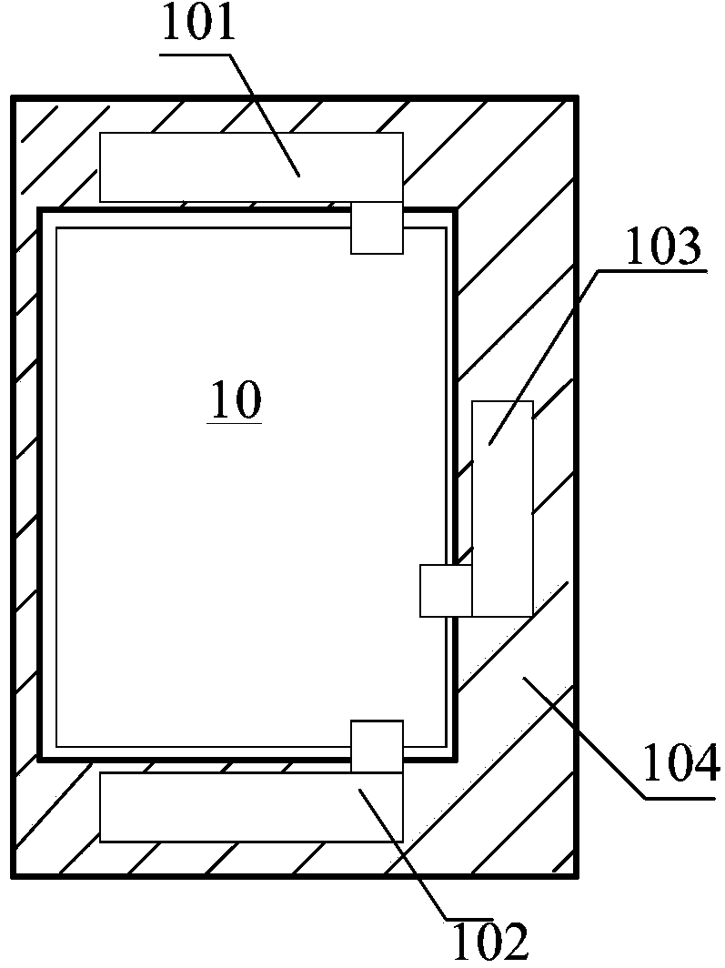
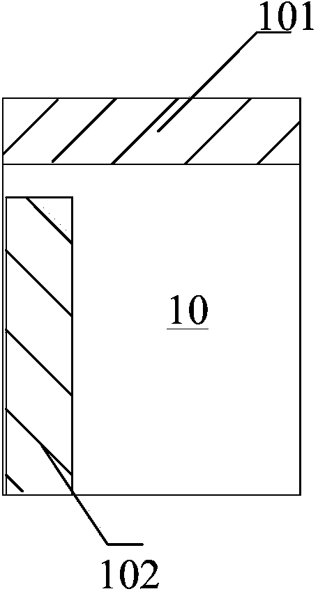
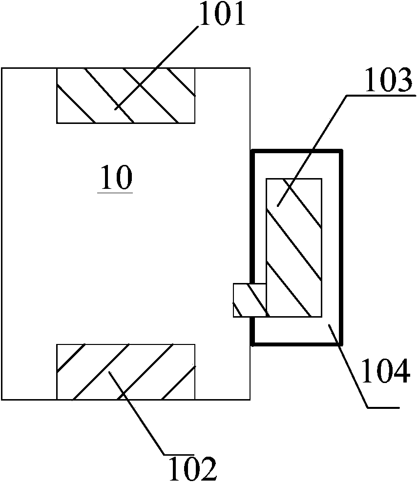
[0030] see Figure 1a ~c is a schematic structural diagram of a wireless terminal in an embodiment of the present invention.

[0031] The wireless terminal includes a PCB 10 , a first antenna 101 , a second antenna 102 , a resonator 103 and a bracket 104 .

[0032] The first antenna 101 is located on one side of the PCB 10, and the second antenna 102 is located on the other side of the PCB 10. Specifically, the first antenna 101 and the second antenna 102 can be respectively located on opposite sides of the PCB 10, such as Fig...


PUM


Abstract

The present invention discloses a wireless terminal. The wireless terminal includes a first antenna, a second antenna, a printed circuit board, a support and a resonator, wherein the first antenna is located at a side of the printed circuit board, the second antenna is located at the other side of the printed circuit board, the printed circuit board is used as a metal ground of the first antenna and the second antenna, the resonator is located on the support, a grounding point of the resonator is located on the printed circuit board, and a clearance zone is disposed between the plurality of antennae and the printed circuit board. The wireless improves an isolation degree of the plurality of anteenae, and the clearance zone is disposed between the resonator and the PCB, so that the resonator is enable to radiate the energy of the antenna in a better way, and the energy of the antenna flow into the resonator is avoided to be comsumped in the resonator, secondary radiation of antenna energy is achieved, and radiation efficiency of the antenna is improved.

Description

technical field [0001] The present invention relates to the field of wireless communication, in particular to a wireless terminal. Background technique [0002] With multi-mode (Global System of Mobile communication (GSM) / Wideband Code Division Multiple Access (WCDMA) / Code Division Multiple Access (CDMA) / Long Term Evolution (Long Term Evolution) Term Evolution, LTE)) and wireless terminals with receive diversity technology are the key development directions of the industry in the future. Due to the limitation of the size of the wireless terminal itself, the distance between multiple antennas on the wireless terminal is relatively close. If the working frequency bands of multiple antennas overlap, mutual coupling will occur between multiple antennas, which will affect the radiation efficiency of each antenna. For example, in a diversity antenna system of a wireless terminal, objectively there is an electromagnetic wave coupling effect between the main antenna and the diversi...

Claims


Application Information

Patent Timeline
IPC IPC(8): H01Q1/52H01Q21/00
CPCH01Q1/243H01Q1/48H01Q1/523H01Q5/371H01Q21/28H01Q1/38H01Q1/521H01Q1/526H01Q5/342H01Q9/0421
Inventor 赵亮王汉阳柳青徐慧梁范毅兰尧隆仲莹屠东兴
Owner HUAWEI DEVICE CO LTD
Why Eureka
Try Eureka