
General clamp for machining blade molded line

A blade profile and fixture technology, used in manufacturing tools, metal processing equipment, metal processing machinery parts, etc., can solve the problems of affecting work efficiency, long debugging time, unstable blade profile processing dimensions, etc., to achieve strong versatility, The effect of improving processing quality

Active Publication Date: 2014-03-19
AECC AERO SCI & TECH CO LTD
View PDF5 Cites 11 Cited by
  • Summary
  • Abstract
  • Description
  • Claims
  • Application Information

AI Technical Summary

Problems solved by technology

from figure 1 It can be seen that due to the structure of the special fixture, there are the following disadvantages: (1) One set of blade tenon root type fixtures of one size will inevitably lead to more fixtures and increase the processing cost; (2) The special fixture uses the back of the blade basin One side is a fixed reference, and the other side is compressed by a compression device. This solution will cause instability in the processing size of the blade profile due to the upper and lower deviations of the blade tenon size; (3) It takes a long time to debug when replacing the processed blade, which affects work efficiency

Method used


Image

  • General clamp for machining blade molded line
  • General clamp for machining blade molded line
  • General clamp for machining blade molded line

Examples


Embodiment 1

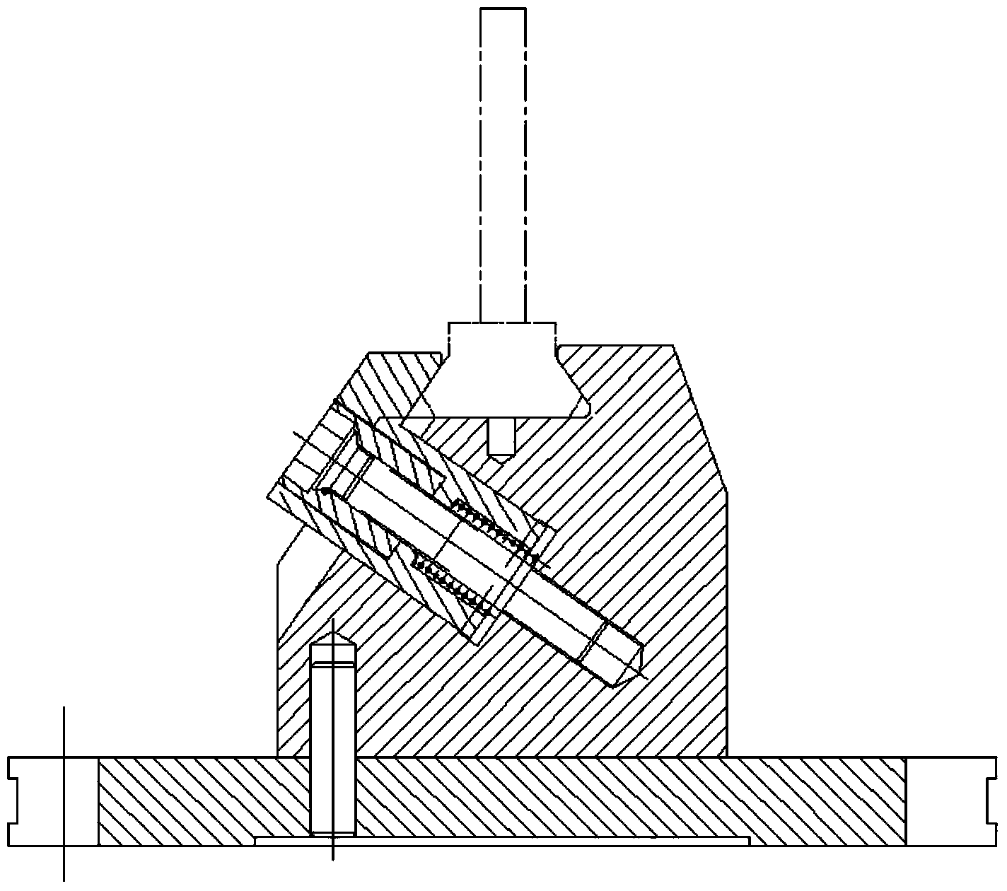
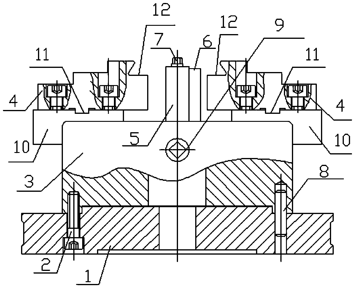
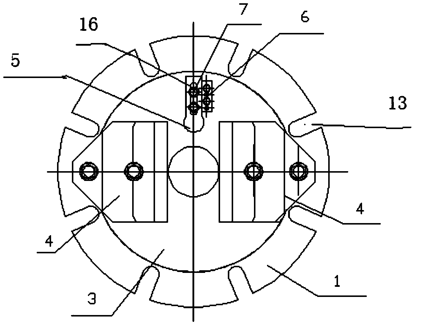
[0039] In this embodiment, the structure of the universal fixture for processing the profile of the blade is as follows: figure 2 , image 3 As shown, it includes a base 1, a self-centering two-jaw chuck, a blade tenon fixing seat 4, an adjustable positioning block 5 and a guide block 6. The structure of base 1 is as follows Figure 4 , Figure 5 As shown, it is a circular seat body, the seat body is provided with a central hole, and its periphery is provided with eight U-shaped grooves 13 equiangularly distributed, and its top surface is provided with a positioning protrusion for installing a self-centering two-jaw chuck. Table 14, the bottom surface of which is provided with grooves to reduce the contact surface with the blade profile processing equipment; the structure of the blade tenon fixing seat 4 is as follows Figure 6 , Figure 7 , Figure 8 As shown, the bottom surface is provided with a positioning structure for installation, and one side is provided with a j...

Embodiment 2

[0044] In this embodiment, the structure of the universal fixture for processing the profile of the blade is as follows: Figure 14 As shown, it includes a base 1 , a self-centering two-jaw chuck, a blade tenon fixing seat 4 , a block 18 , an adjustable positioning block 5 and a guide block 6 . The difference from Embodiment 1 is that two blocks 18 are added, and the two blocks are respectively installed on the sides of the two blade tenon fixing seats 4 facing the center of the self-centering two-jaw chuck body 3, and the two blocks are The provided jaws 12 are directed toward the center of the body 3 of the self-centering two-jaw chuck.

[0045] The universal jig for processing blade profiles described in this embodiment only needs to replace two blocks 18 instead of two blade tenon fixing seats 4 when the tenon root shape of the blade to be processed is changed.


PUM


Abstract

A general clamp for machining a blade molded line comprises a base, a self-centering two-claw chuck, blade tenon fixing bases, an adjustable locating block and a guiding block or a base, a self-centering two-claw chuck, blade tenon fixing bases, molded blocks, an adjustable locating block and a guiding block. The self-centering two-claw chuck is arranged on the base, the two blade tenon fixing bases are arranged two claw top faces of the self-centering two-claw chuck, and the two molded blocks are arranged on the lateral sides of the two blade tenon fixing bases facing the self-centering two-claw chuck body center. The adjustable locating block is arranged on a self-centering two-claw chuck body. The installing position of the adjustable locating block on the chuck body enables the center line of a strip groove to be perpendicular to the center line of the two claws. The guiding block is arranged on the self-centering two-claw chuck body, and a guiding face of the guiding block is in contact with the lateral side of the adjustable locating block.

Description

technical field [0001] The invention belongs to the field of fixtures, in particular to a universal fixture for processing blade profiles. Background technique [0002] The blade is an indispensable part of the engine, gas turbine, fan and other equipment. The traditional blade profile processing fixture is a special fixture designed according to the shape and size of the tenon of the blade, that is, a set of fixtures is designed for a tenon root blade of one size. The structure of the traditional blade profile processing fixture is as follows: figure 1 shown. From figure 1 It can be seen that due to the structure of the special fixture, there are the following disadvantages: (1) One set of blade tenon root type fixtures of one size will inevitably lead to more fixtures and increase the processing cost; (2) The special fixture uses the back of the blade basin One side is a fixed reference, and the other side is compressed by a compression device. This solution will cause ...

Claims


Application Information

Patent Timeline
Patent Type & Authority Applications(China)
IPC IPC(8): B23Q3/00
CPCB23Q3/062
Inventor 罗培真刘建吴华田罡李惠王春笋高辉温兴旺
Owner AECC AERO SCI & TECH CO LTD
Features
  • Generate Ideas
  • Intellectual Property
  • Life Sciences
  • Materials
  • Tech Scout
  • Unparalleled Data Quality
  • Higher Quality Content
  • 60% Fewer Hallucinations
Learn More