
Automatic transfer robot applicable to automatic barrel discharging of glass fibers and working method thereof

A robot and automatic unloading technology, which is applied in the direction of conveying filamentous materials, thin material processing, transportation and packaging, etc., can solve the problems that affect the product processing efficiency and product quality, the operator's work intensity is high, and the production cost is increased. Product processing consistency is good, the effect of reducing the degree of manual intervention and reducing work intensity

Active Publication Date: 2014-03-19
JUSHI GROUP CHENGDU +1
View PDF4 Cites 12 Cited by
  • Summary
  • Abstract
  • Description
  • Claims
  • Application Information

AI Technical Summary

Problems solved by technology

[0002] At present, the glass fiber industry mostly uses manual work to take out the glass fiber wound by the wire drawing machine and put it into the logistics trolley, so that the glass fiber unloading work is completely manual operation, and the operator manually completes the separation of the glass fiber from the wire drawing machine, the A series of processes such as transfer, pairing of glass fiber and logistics trolley, storage of glass fiber, etc., the operator's work intensity is high and the consistency is not high, which affects the product processing efficiency and product quality. At the same time, the use of manual labor increases the production cost and restricts large-scale production

Method used


Image

  • Automatic transfer robot applicable to automatic barrel discharging of glass fibers and working method thereof
  • Automatic transfer robot applicable to automatic barrel discharging of glass fibers and working method thereof
  • Automatic transfer robot applicable to automatic barrel discharging of glass fibers and working method thereof

Examples


Embodiment Construction

[0026] The present invention will be further described below in conjunction with accompanying drawing, protection scope of the present invention is not limited to the following:

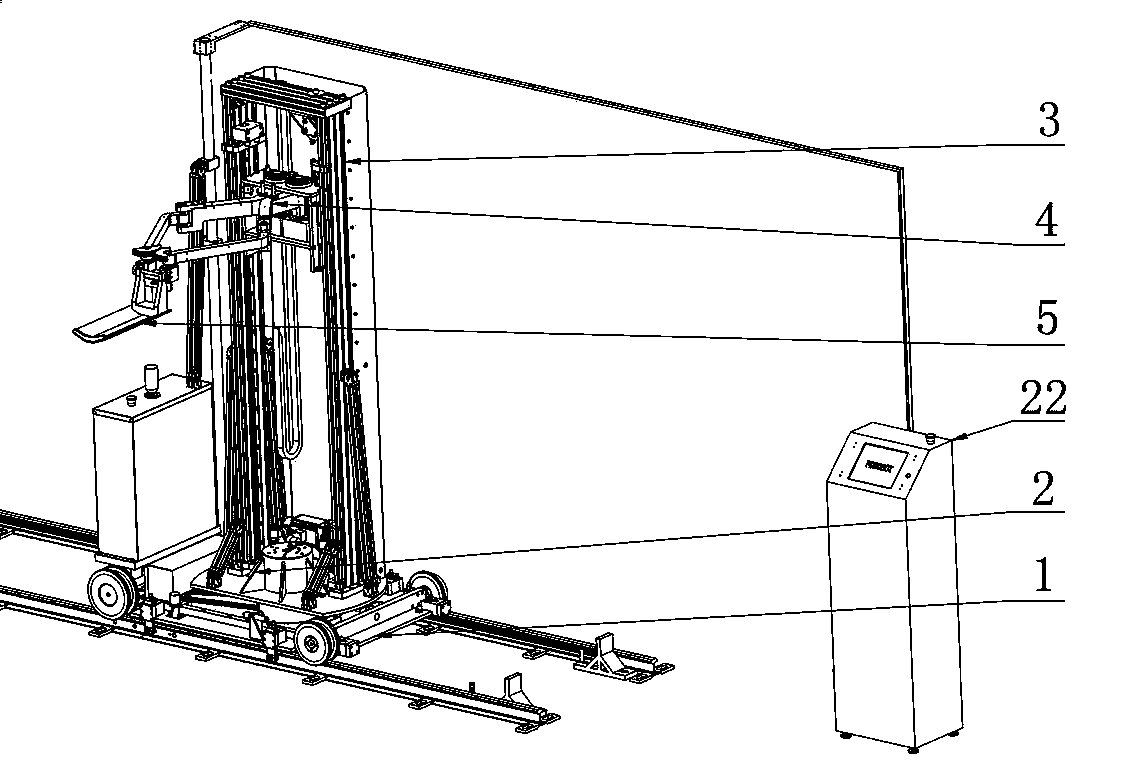
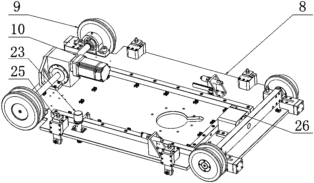
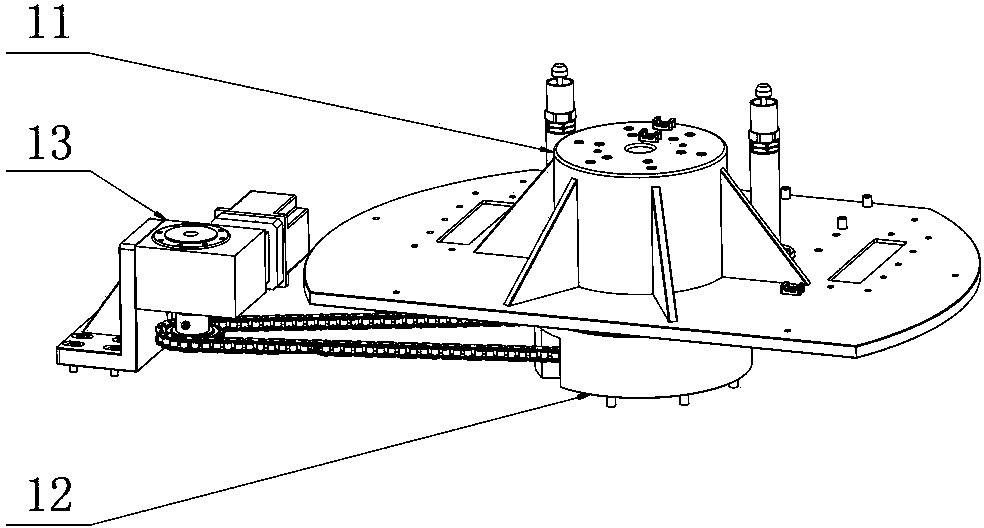
[0027] like figure 1 As shown, the automatic transfer robot suitable for glass fiber automatic unloading cylinders includes a traveling mechanism 1, a rotating mechanism 2, a lifting mechanism 3, a telescopic mechanism 4 and a hopper 5, and the rotating mechanism 2 rotating around a vertical axis is installed on the traveling mechanism 1 Above, the lifting mechanism 3 is installed on the rotating mechanism 2, the lifting mechanism 3 includes a sliding part 6 for vertical lifting, the telescopic mechanism 4 is fixedly installed on the sliding part 6, the telescopic mechanism 4 includes a telescopic arm 7 that expands and contracts in the horizontal direction, and the hopper 5 is fixedly installed at the end of the telescopic arm. The traveling mechanism 1 can move on the ground or on the track; the r...


PUM


Abstract

The invention discloses an automatic transfer robot applicable to automatic barrel discharging of glass fibers. The automatic transfer robot comprises a walking mechanism (1), a rotating mechanism (2), a lifting mechanism (3), a telescoping mechanism (4) and a hopper (5). The rotating mechanism (2) rotating around the perpendicular axis is installed on the walking mechanism (1), the lifting mechanism (3) is installed on the rotating mechanism (2), the lifting mechanism (3) comprises a perpendicularly lifting sliding part (6), the telescoping mechanism (4) is fixedly installed on the sliding part (6), the telescoping mechanism (4) comprises telescopic arms (7) telescoping in the horizontal direction, and the hopper (5) is fixedly installed at the ends of the telescopic arms. The invention further discloses a working method of the automatic transfer robot. The automatic transfer robot applicable to automatic barrel discharging of glass fibers and the working method of the automatic transfer robot have the advantages that full-automatic barrel discharging work of the glass fibers can be achieved, the automatic transfer robot can adapt to exiting glass fiber production equipment to the maximum extent and is high in automation degree and good in product machining consistency, production efficiency is improved, and the work intensity of workers is relieved.

Description

technical field [0001] The invention relates to the technical field of glass fiber transfer equipment, in particular to an automatic transfer robot suitable for automatic glass fiber unloading barrels and a working method thereof. Background technique [0002] At present, the glass fiber industry mostly uses manual work to take out the glass fiber wound by the wire drawing machine and put it into the logistics trolley, so that the glass fiber unloading work is completely manual operation, and the operator manually completes the separation of the glass fiber from the wire drawing machine, the For a series of processes such as transferring, pairing of glass fiber and logistics trolley, and storage of glass fiber, the operator's work intensity is high and the consistency is not high, which affects product processing efficiency and product quality. At the same time, manual use increases production costs and restricts large-scale production. Contents of the invention [0003] T...

Claims


Application Information

Patent Timeline
Patent Type & Authority Applications(China)
IPC IPC(8): B65H67/06
Inventor 李波郭明兵陈杰陈刚吴军胡天链赖健
Owner JUSHI GROUP CHENGDU
Learn More