Pulley high-low position adjustment method based on sliding door application and sliding door adjusting device

A technology of an adjusting device and an adjusting method, which is applied to the suspension device of the wing leaf, door/window fittings, wing leaf components, etc., can solve the problems of affecting the overall design of the sliding door, inconvenient adjustment, and difficulty in adjustment, etc., and achieves a simple structure. , The effect of low manufacturing cost and safe use

Inactive Publication Date: 2014-03-19
东莞市荣翘泰五金有限公司
View PDF11 Cites 9 Cited by
  • Summary
  • Abstract
  • Description
  • Claims
  • Application Information

AI Technical Summary

Problems solved by technology

[0002] Sliding doors have become one of the most widely used home decorations. They are mostly used for house design or installation on various boxes and cabinets. The sliding doors themselves have a large structure and are easy to use. Noise, and easy to install and disassemble. During the installation or use of the sliding door, the height needs to be adjusted. It needs to be realized by the sliding door adjustment device installed under the sliding door. At present, the traditional sliding door adjuster realizes The adjustment hole for position adjustment is mostly set on the top, which is very inconvenient during the adjustment process, that is, the fixed adjustment hole is set on the top of the device. To adjust the height of the sliding door, you need to take out the device and use a screwdriver or wrench to turn the screw to adjust it. Reinstallation, or setting a special adjustment position at the installation position of the equipment, makes the adjustment difficult and inconvenient. If a special adjustment space is reserved for adjustment, it will affect the overall design of the sliding door , affecting its normal use

Method used


Image

  • Pulley high-low position adjustment method based on sliding door application and sliding door adjusting device
  • Pulley high-low position adjustment method based on sliding door application and sliding door adjusting device
  • Pulley high-low position adjustment method based on sliding door application and sliding door adjusting device

Examples


Embodiment 1

[0033] like figure 1 , figure 2 and image 3 As shown, a method for adjusting the height of the pulley based on the application of the sliding door in this embodiment includes the following steps:

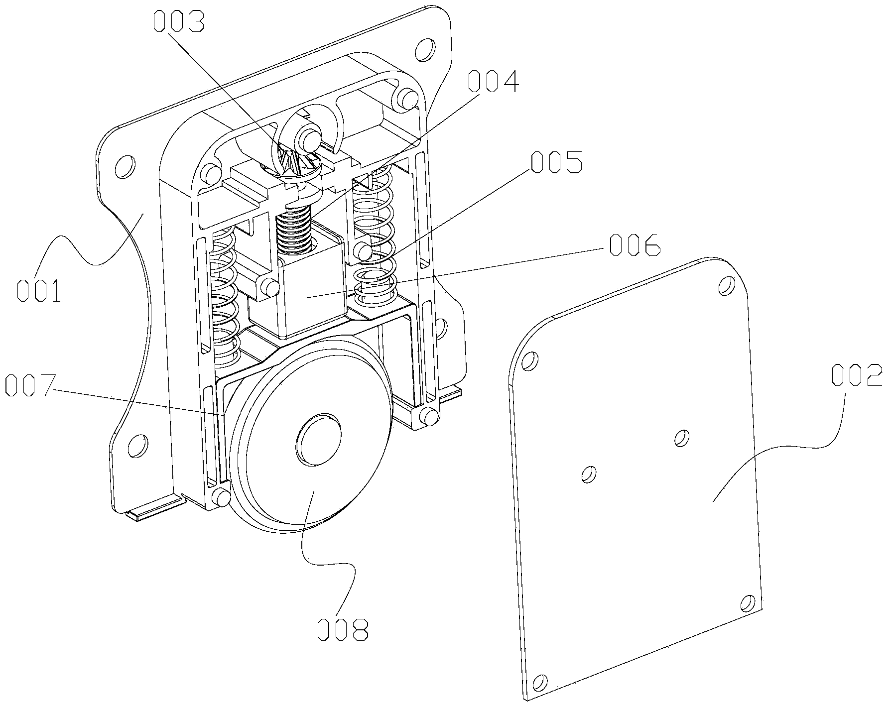
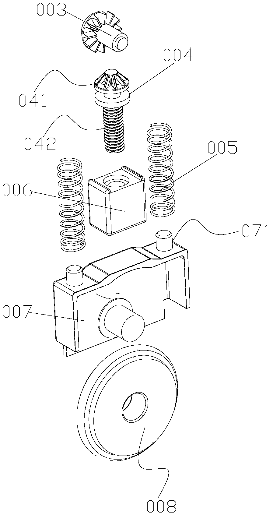
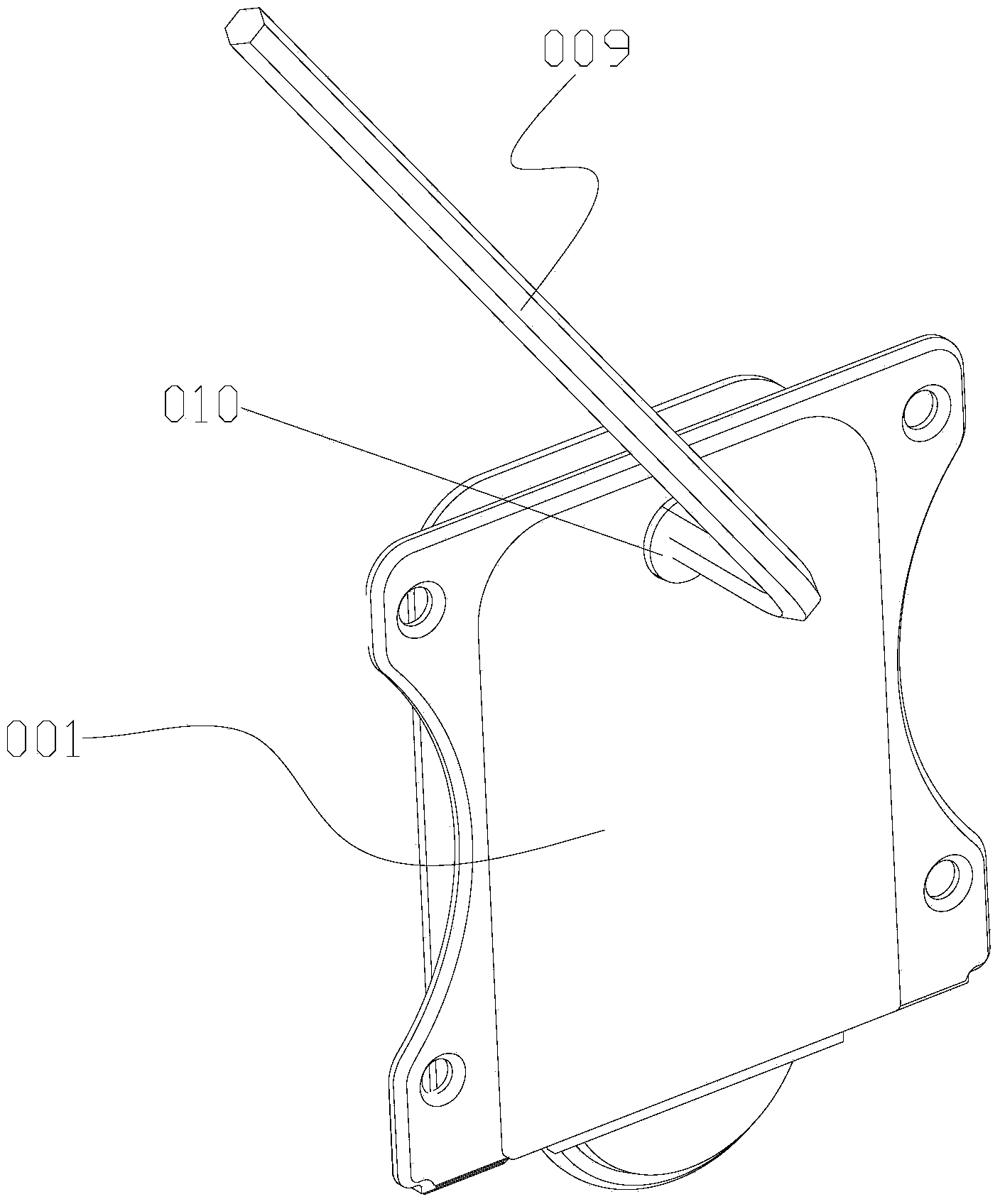
[0034] (1) A sliding door adjustment device, an adjustment wheel 008 and a wrench 009 are provided, and a horizontal adjustment mechanism is arranged inside the sliding door adjustment device; the adjustment wheel 008 is arranged under the sliding door adjustment device, and the sliding door adjustment device also includes Externally fixed casing 001 and cover plate 002, the inner cavity of the casing 001 is a cavity for accommodating the lateral adjustment mechanism, and the wrench 009 is a hexagonal wrench.

[0035] (2) The horizontal adjustment mechanism is composed of interlocking horizontal gear 003, bevel tooth screw 004, thread slider 006, bearing slider 007 and spring 005; the horizontal gear 003 is set on the upper end of the bevel tooth screw 004, The bevel tooth scre...


PUM


Abstract

The invention discloses a pulley high-low position adjustment method based on sliding door application. A horizontal gear and a taper tooth screw are in close fit with each other; when the height of a gap between a door panel and a cabinet body needs to be adjusted, the horizontal gear is driven to rotate by a hexagon spanner and drives the taper tooth screw to rotate, and the taper tooth screw rotates left and right to drive a threaded slide block to lift up and down, so that a bearing slide block is pushed to lift up and down to realize up-and-down lifting of an adjusting wheel, and accordingly, the gap between the cabinet body and the door panel can be adjusted. The traditional vertical adjustment method is changed in the way that the horizontal gear is adjusted to realize height adjustment of the sliding door, and the adjustment is quick and convenient. The invention also discloses a sliding door adjusting device which has a simple structure, successfully converts vertical adjustment into horizontal adjustment, is low in manufacturing cost and convenient in use, can effectively prevent an adjusting wheel from jumping on a rail, and is safer in use.

Description

technical field [0001] The invention relates to a sliding door adjustment technology, in particular to a method for adjusting the height of a pulley based on the application of a sliding door, and more particularly to a sliding door adjustment device for realizing the method. Background technique [0002] Sliding doors have become one of the most widely used home decorations. They are mostly used for house design or installation on various boxes and cabinets. The sliding doors themselves have a large structure and are easy to use. Noise, and easy to install and disassemble. During the installation or use of the sliding door, the height needs to be adjusted. It needs to be realized by the sliding door adjustment device installed under the sliding door. At present, the traditional sliding door adjuster realizes The adjustment hole for position adjustment is mostly set on the top, which is very inconvenient during the adjustment process, that is, the fixed adjustment hole is se...

Claims


Application Information

Patent Timeline
Patent Type & Authority Applications(China)
IPC IPC(8): E05D13/00
CPCE05D15/0673E05D15/0669E05Y2201/612E05Y2201/614E05Y2201/616E05Y2201/718E05Y2900/20
Inventor 谭伟球黄海明
Owner 东莞市荣翘泰五金有限公司
Why Eureka
Try Eureka