Eureka AIR delivers breakthrough ideas for toughest innovation challenges, trusted by R&D personnel around the world.

An automatic pressure injection device and method for lubricating drag reducing mud for pipe jacking

An automatic, muddy technology, applied in pipeline laying and maintenance, pipes/pipe joints/fittings, mechanical equipment, etc., can solve the problems of inability to precisely control the amount of grouting, poor grouting effect, high labor intensity, etc. The effect of slurry lubrication, preventing pipe collapse and reducing labor intensity

Active Publication Date: 2015-11-18
中铁市政环境建设有限公司
View PDF7 Cites 0 Cited by
  • Summary
  • Abstract
  • Description
  • Claims
  • Application Information

AI Technical Summary

Problems solved by technology

At present, most of the existing pipe jacking grouting is manual grouting, and each process of ingredients, grouting pressure, and grouting amount needs a special person to be responsible for accurately controlling the grouting pressure, grouting time, and grouting amount. Operating manual valves, with a large number and scattered layout, requires frequent movement back and forth in the pipeline, resulting in the inability to accurately control the amount of grouting, high labor intensity, poor grouting effect, and low operating efficiency.

Method used


Image

  • An automatic pressure injection device and method for lubricating drag reducing mud for pipe jacking
  • An automatic pressure injection device and method for lubricating drag reducing mud for pipe jacking
  • An automatic pressure injection device and method for lubricating drag reducing mud for pipe jacking

Examples


Embodiment 1

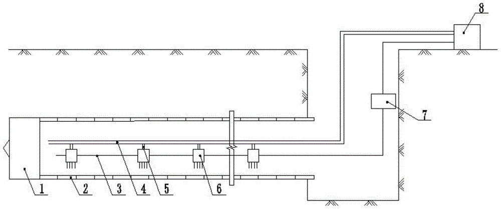
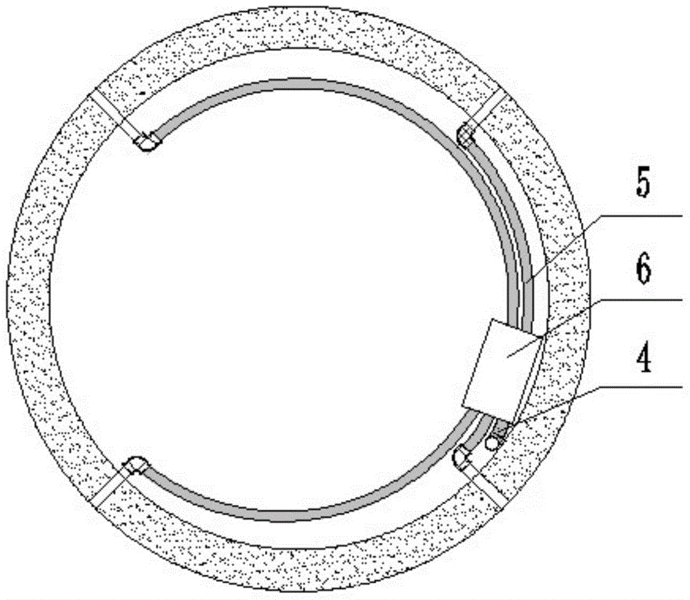
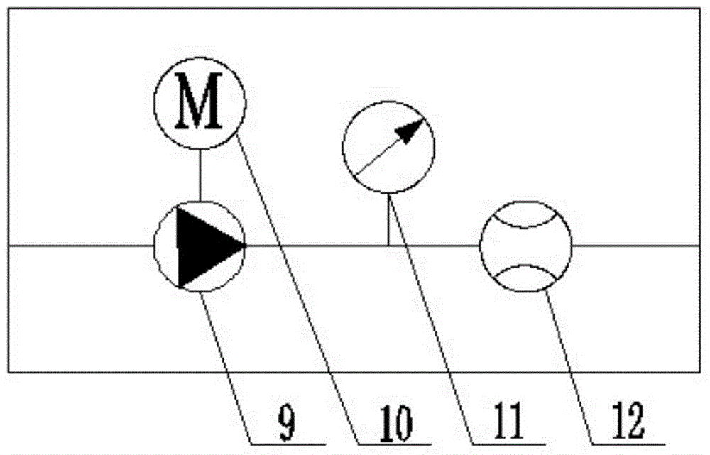
[0025] Such as figure 1 , figure 2 As shown, the automatic pressure injection device for lubricating and drag-reducing mud for pipe jacking of the present invention includes main parts such as control cables 3, main grouting pipes 4, sub-pipes for grouting 5, valve stations 6, centralized control boxes 7 and pumping stations, and the centralized control box 7 Control the pumping station and valve station 6 through the control cable 3, the grouting pump 9 sucks the drag-reducing mud and discharges it from the outlet of the pump, and then passes through the speed regulating motor 10, electromagnetic flowmeter 11, pressure sensor 12, The slurry main pipe 4 and the grouting branch pipe 5 are transported into the pipe, and the valve stations 6 are sequentially distributed in the jacking pipe. Corresponding grouting parameters on the grouting main pipe 4 and the grouting branch pipe 5 transmit data through the control cable 3, which is convenient for personnel to observe and recor...

Embodiment 2

[0030] The automatic pressure injection method of the lubricating and drag-reducing mud automatic pressure injection device for pipe jacking is adopted. The work of the valve station is the key to grouting. , install a valve station in the pipe every about 30m. During the jacking process of the whole line, the tail grouting is in the normally open state. Assuming that n valve stations are installed along the line, first open the n# valve station, every 4 The unit time is 5s ahead of the n-1# valve station. After continuing to jack up for 35m, assuming that it is opened to the m# (m

[0031] For the single-point valve station, the 0# main valve is in the normally open state, and then the 1# to 4# electric ball valves are opened in turn, and the 2# electric ball valve is opened 5 seconds before the 1# electric ball valve is clo...


PUM


Abstract

The invention relates to the technical field of engineering construction, in particular to an automatic pressure feeding device and method for lubricating and drag-reduction slurry for push pipes. The device comprises a push bench, pipe units, a control cable, a slurry feeding main pipe, slurry feeding branch pipes, valve stations, a central control box and a pump station, wherein the pipe units are arranged behind the push bench; slurry feeding pipes are arranged in the pipe units and comprises one slurry feeding main pipe and a plurality of slurry feeding branch pipes; a plurality of valve stations are arranged on the slurry feeding main pipe, each valve station comprises a slurry feeding main pipe, slurry feeding branch pipes, slurry feeding branch valves, a slurry feeding master valve and a remote control box which is connected with the slurry feeding master valve and the slurry feeding branch valves through signal wires. Compared with the prior art, the device has the advantages that remote central control, the central control box and the control cable are adopted to directly control the slurry feeding process, so as to avoid various disadvantages caused by manual operation, improve the construction efficiency, accelerate operation response, reduce labor intensity and improve lubricating effect of fed slurry, and as a result, the slurry feeding amount is stable and the slurry feeding process is efficient.

Description

[technical field] [0001] The invention relates to the technical field of engineering construction, in particular to an automatic injection device and method for lubricating drag-reducing mud for pipe jacking. [Background technique] [0002] Grouting is a key step in the construction process of the project. The purpose of grouting is to improve the loose properties of the disturbed soil layer around the pipe wall in the pipe jacking, to increase the compressive strength and cohesiveness of the top and side of the pipe, and to achieve the purpose of reinforcement. , to prevent road subsidence and ensure the safety of the pipeline. The main function of lubricating drag-reducing mud during pipe jacking construction is to form a mud sleeve during the jacking process to reduce the friction with the surrounding soil, thereby reducing the jacking resistance. The quality of the grouting project needs to be strictly controlled in accordance with the relevant national technical specif...

Claims


Application Information

Patent Timeline
Patent Type & Authority Patents(China)
IPC IPC(8): F16L1/028
CPCF16L1/028
Inventor 吴杭州邓永驰孙焕斌王靖张海涛刘广超
Owner 中铁市政环境建设有限公司
Why Eureka
Eureka Blog
Learn More