
A high temperature solar heat absorber

A technology of solar heat absorber and high temperature, which is applied in the direction of solar heat collector, solar thermal energy, solar thermal power generation, etc. It can solve the problems of reduced heat insulation and sealing performance of optical windows, reduced service life of heat absorber, deformation of inlet flange, etc. problems, to achieve the effect of sealing installation, prolonging service life and reducing air leakage rate

Active Publication Date: 2015-08-19
HARBIN INST OF TECH
View PDF7 Cites 0 Cited by
  • Summary
  • Abstract
  • Description
  • Claims
  • Application Information

AI Technical Summary

Problems solved by technology

[0003] The present invention aims to solve the problem that the high-temperature and high-pressure environment of several or even more than ten atmospheres often occurs inside the current solar heat absorber, which reduces the heat insulation and sealing performance of the optical window, and at the same time, the inlet flange will be deformed and the internal sealing material will deteriorate. The technical problem of broken windows and significantly reduced service life of the entire heat absorber, thereby providing a high temperature solar heat absorber

Method used


Image

  • A high temperature solar heat absorber
  • A high temperature solar heat absorber
  • A high temperature solar heat absorber

Examples


specific Embodiment approach 1

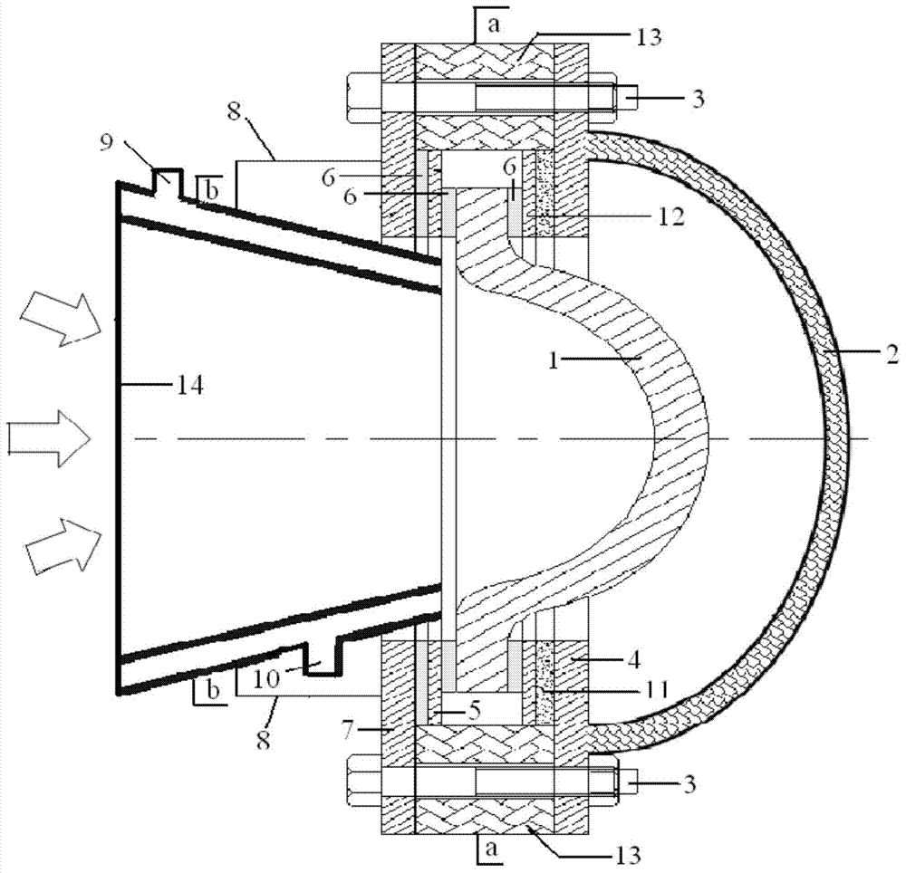
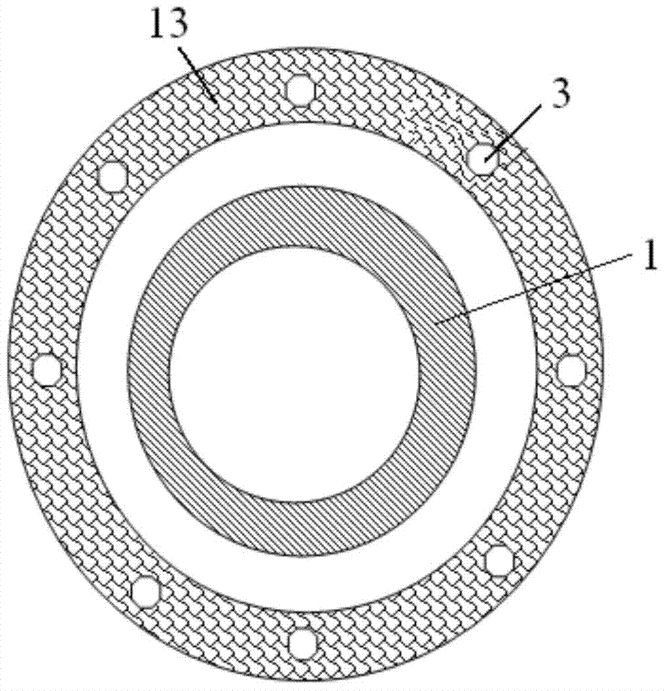
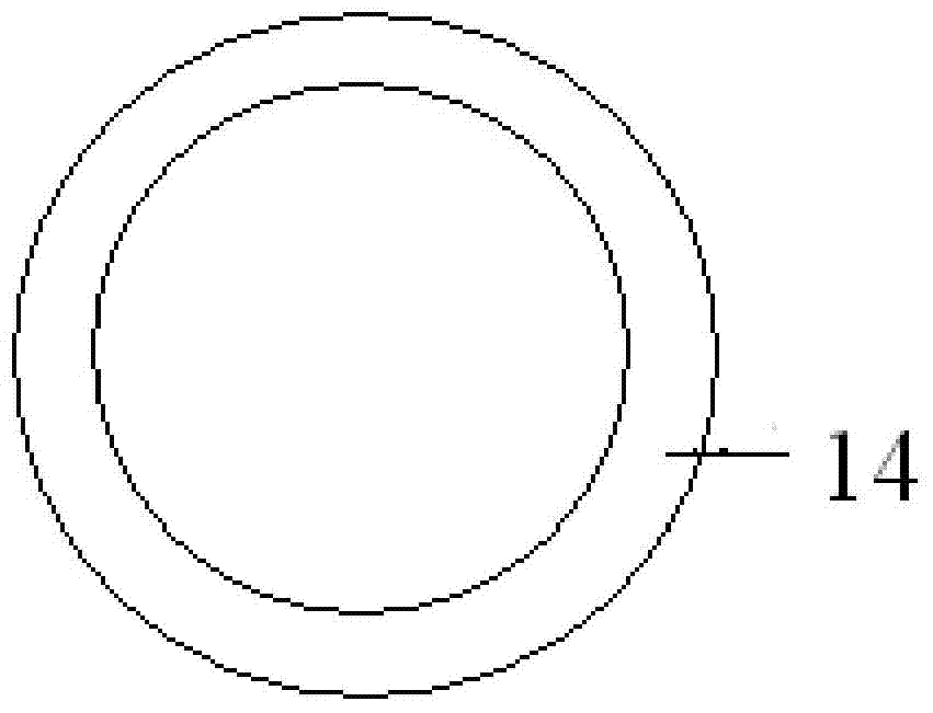
[0022] Specific implementation mode one: combine Figure 1-3 , a high-temperature solar heat absorber of the present embodiment, which includes a heat-absorbing cavity 2 and a semi-ellipsoidal optical window 1, and is characterized in that it also includes a high-temperature-resistant resin glue 6, an annular inner metal sheet 12, and an annular outer metal sheet 5 , annular ceramic fiber mat 11, annular inner flange 4, annular outer flange 7, bolts 3, annular graphite gasket 13, frustum-shaped water-cooled target stage 14 and target stage support 8; semi-ellipsoidal optical window 1 has an annular platform , the semi-ellipsoid shape of the semi-ellipsoidal optical window 1 is smoothly transitioned to the annular platform, and the annular inner metal sheet 12 and the annular outer metal sheet 5 are respectively connected to the semi-ellipsoidal optical window with the annular platform through the high temperature resistant resin glue 6. The upper and lower planes of the annula...

specific Embodiment approach 2

[0037] Embodiment 2: The difference between this embodiment and Embodiment 1 is that the materials of the annular inner flange 4 and the annular outer flange 7 are both steel. Others are the same as the first embodiment.

specific Embodiment approach 3

[0038] Embodiment 3: The difference between this embodiment and Embodiment 1 or 2 is that: the materials of the annular inner metal sheet 12 and the annular outer metal sheet 5 are both steel. Others are the same as those in the first or second embodiment.


PUM


Abstract

The invention discloses a high temperature solar energy thermal absorber, relates to a solar energy thermal absorber, and aims to solve the technical problems that the thermal insulation and air tightness properties of an optic window are reduced, an inlet flange is deformed, an inner sealing material is degenerated, the window is broken, and the service life of the whole thermal absorber is remarkably shortened, which are caused by the fact that a high temperature and high pressure environment with several or even dozens of atmospheric pressures is formed inside a conventional solar energy thermal absorber. The temperature solar energy thermal absorber comprises the optic window, sheet metals, a ceramic fiber blanket, flanges, a graphite spacer, and a water cooled target platform, wherein the sheet metals are connected with the optic window through high temperature resistant resin adhesive; the outer side flange and the outer side metal sheet are connected through high temperature resistant resin adhesive; the ceramic fiber blanket is clamped between the inner side flange and the inner side sheet metal; the graphite spacer is clamped on the outer side of a part between the inner side flange and the outer side flange; a water inlet is formed in the lower part of the water cooled target platform; a water outlet is formed in the upper part of the water cooled target platform. The high temperature solar energy thermal absorber is mainly applied to the field of solar energy.

Description

technical field [0001] The invention relates to a solar heat absorber. Background technique [0002] The solar energy resource is abundant, clean and easy to obtain. The high-temperature solar thermal utilization system adopts solar concentrators to obtain high-power concentrated energy flow. The volumetric absorber adopts a closed and sealed structure to convert the received concentrated solar radiation into heat energy and transfer it to the heat carrier. . The high-temperature solar thermal utilization system has been widely used in solar thermal demonstration power plants. The radiation heating of the internal ceramic materials can make the heated air medium generate high temperatures as high as 1000 °C. The optical window at the entrance has the functions of absorbing and concentrating solar radiation, and isolating the heat absorber from the external space. There are often several or even tens of atmospheres of high temperature and high pressure inside the heat absor...

Claims


Application Information

Patent Timeline
Patent Type & Authority Patents(China)
IPC IPC(8): F24J2/05F24J2/46F24J2/48F24J2/51F24S10/40
CPCF24J2/07Y02E10/44F24S20/20Y02E10/40
Inventor 夏新林孟宪龙李鹏董献宏孙创
Owner HARBIN INST OF TECH
Learn More