
Method and system for sea-clutter restraining and target detection in sea-clutter background

A sea clutter and dispersion relationship technology, applied in the field of radar, can solve the problems of unsuitable detection and inaccurate detection of targets, and achieve the effect of suppressing sea clutter and improving accuracy

Active Publication Date: 2014-03-19
BEIJING INST OF ENVIRONMENTAL FEATURES
View PDF3 Cites 18 Cited by
  • Summary
  • Abstract
  • Description
  • Claims
  • Application Information

AI Technical Summary

Problems solved by technology

[0005] However, the inventors of the present invention have found that the existing sea surface target detection method is not applicable to the detection of the target by the sea surface search radar equipped on the mobile radar irradiation platform, because the movement of the sea surface search radar will affect the actual measured space- The Doppler frequency shift is introduced into the time image, which makes the space-time image measured by the sea surface search radar and the space-time image measured by the shore-based sea-observation radar of the staring system have a large deviation in the space-time dispersion relationship. The intrinsic spatio-temporal dispersion relation of the wave, the space-time sea clutter elimination of the spatio-temporal dispersion relation contained in the image cannot have a good effect, and the target cannot be accurately detected

Method used


Image

  • Method and system for sea-clutter restraining and target detection in sea-clutter background
  • Method and system for sea-clutter restraining and target detection in sea-clutter background
  • Method and system for sea-clutter restraining and target detection in sea-clutter background

Examples


Embodiment Construction

[0063] In order to make the object, technical solution and advantages of the present invention clearer, the present invention will be described in further detail below with reference to the accompanying drawings and preferred embodiments. However, it should be noted that many of the details listed in the specification are only for readers to have a thorough understanding of one or more aspects of the present invention, and these aspects of the present invention can be implemented even without these specific details.

[0064] As used herein, terms such as "module" and "system" are intended to include computer-related entities such as, but not limited to, hardware, firmware, a combination of hardware and software, software, or software in execution. For example, a module may be, but is not limited to being limited to being, a process running on a processor, a processor, an object, an executable, a thread of execution, a program, and / or a computer. For example, both an applicatio...


PUM


Abstract

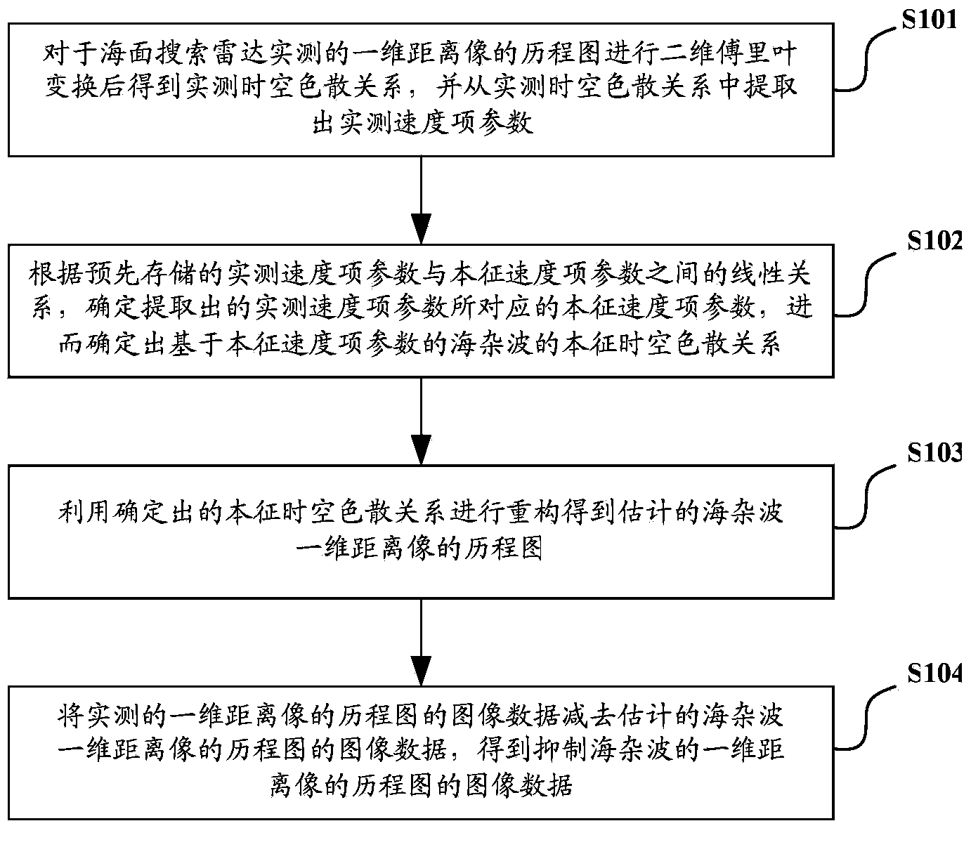
The invention discloses a method and system for sea-clutter restraining and target detection in a sea-clutter background. The sea-clutter restraining method includes: performing two-dimensional Fourier transformation on a history plot of a one-dimensional range profile, which is detected by a sea-surface search radar in a real-time manner and obtaining a real-time-detection space-time dispersion relation and extracting real-time-detection speed parameters from the real-time-detection space-time dispersion relation; according to a linear relation between the real-time-detection speed parameters and intrinsic speed parameters, determining intrinsic speed parameters corresponding to the real-time-detection speed parameters and determining an intrinsic space-time diversion relation of sea clutters, which is based on the intrinsic-speed parameters; performing reconstruction through use of the determined intrinsic space-time diversion relation and obtaining an estimated history plot of the one-dimensional range profile of the sea clutters; and subtracting image data of the estimated history plot of the one-dimensional range profile of the sea clutters from image data of the real-time-detection history plot of the one-dimensional range profile and obtaining image data of a sea-clutter-restraining history plot of the one-dimensional range profile. Therefore, the sea flutters are restrained better and accuracy of target detection in the sea-clutter background is improved.

Description

technical field [0001] The invention relates to radar technology, in particular to a method and system for sea clutter suppression and target detection in the sea clutter background. Background technique [0002] Radar is an electronic device that uses electromagnetic waves to detect targets. It emits electromagnetic waves to irradiate the target and receives its echoes, thereby obtaining information such as the distance from the target to the electromagnetic wave emission point, the distance change rate (radial velocity), azimuth, and height. [0003] When the radar detects the target, the radar receives not only the echo of the target, but also superimposes the echo of the unwanted illuminated area. This part of the echo is called clutter in radar terms; when the radar detects the target located on the sea surface When , the echo from the sea surface, that is, sea clutter, will affect the detection of the target on the sea surface. [0004] British scholar K.D. Ward et al...

Claims


Application Information

Patent Timeline
IPC IPC(8): G01S7/41
CPCG01S7/414G01S13/89
Inventor 元旭津陈勇董纯柱王超殷红成
Owner BEIJING INST OF ENVIRONMENTAL FEATURES
Learn More