Non-overlapping clock generation circuit

A clock generation circuit, non-overlapping technology, applied in the direction of electric pulse generator circuit, etc., can solve the problems of data error, signal axis interference, etc.

Active Publication Date: 2014-03-19
HANGZHOU SILAN MICROELECTRONICS
View PDF4 Cites 3 Cited by
  • Summary
  • Abstract
  • Description
  • Claims
  • Application Information

AI Technical Summary

Problems solved by technology

If there is an overlap between the time-sharing selection clocks at this time, it will cause the mechanical part and the analog part of the sensor to generate signal inter-axis interference during time-sharing processing, resulting in errors in the measured data

Method used


Image

  • Non-overlapping clock generation circuit
  • Non-overlapping clock generation circuit
  • Non-overlapping clock generation circuit

Examples


Embodiment 1

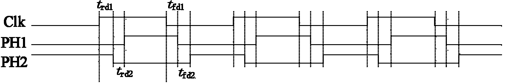
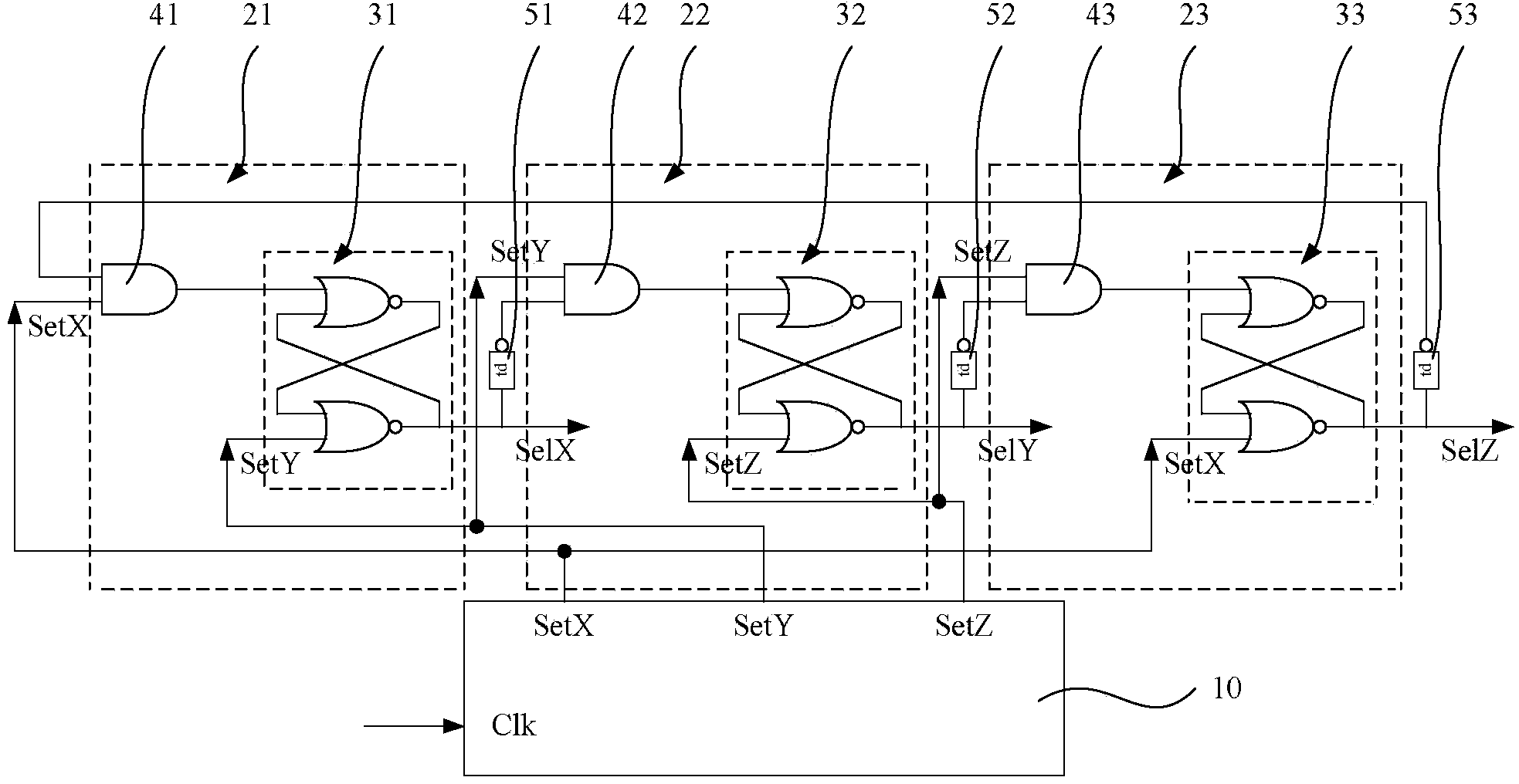
[0029] In the first embodiment, the non-overlapping clock generation circuit can generate three non-overlapping clocks. For details, please refer to image 3 and Figure 4 ,in, image 3 is a schematic diagram of a non-overlapping clock generation circuit according to an embodiment of the present invention; Figure 4 It is a timing diagram of three-phase non-overlapping clocks generated by the non-overlapping clock generation circuit of the embodiment of the present invention.

[0030] Such as image 3 As shown, in this embodiment, the non-overlapping clock generation circuit includes: a finite state machine 10 and three trigger circuits connected to the finite state machine 10;

[0031] The finite state machine 10 can sequentially generate three driving clocks according to the basic clock Clk, which are respectively the first driving clock SetX, the second driving clock SetY and the third driving clock SetZ;

[0032] The 3 trigger circuits are respectively a first trigger ...

Embodiment 2

[0044] Please refer to Figure 5 and Figure 6 ,in, Figure 5 It is a schematic diagram of connection of n trigger circuits in Embodiment 2 of the present invention; Figure 6 It is a schematic diagram of a finite state machine generating n driving clocks according to Embodiment 2 of the present invention. Here, for the sake of illustration clarity, the n trigger circuits and the finite state machine are divided into two diagrams for illustration, specifically, Figure 6 The generated drive clock is supplied to the Figure 5 The set or reset terminals shown, for example, Figure 6 The first driving clock Setφ shown in 1 respectively provided to the set end of the first flip-flop in the first flip-flop circuit 61 and the reset end of the nth flip-flop in the nth flip-flop circuit 6n.

[0045] According to the above three-phase non-overlapping clock generating circuit and Figure 5 and Figure 6 It can be seen that when it is necessary to generate n-phase non-overlapping...


PUM


Abstract

The invention provides a non-overlapping clock generation circuit. The circuit comprises a finite-state machine and n trigger circuits which are connected with the finite-state machine. The finite-state machine can successively generate n driving clocks according to a basic clock, wherein the n driving clocks are a first driving clock, a second driving clock,..., and a nth driving clock. The n trigger circuits are a first trigger circuit, a second trigger circuit,..., and a nth trigger circuit. Each trigger circuit comprises an AND gate and a trigger. An output terminal of the AND gate is connected with a setting terminal of the trigger. Through the finite-state machine, according to the basic clock, the n driving clocks are generated. Each trigger circuit generates a non-overlapping clock through accessing the driving clocks and an inversion signal of an output signal of the previous trigger circuit. Therefore, generation of the more than three-phase non-overlapping clock is realized.

Description

technical field [0001] The invention relates to the technical field of clock circuits, in particular to a non-overlapping clock generation circuit. Background technique [0002] Two-phase non-overlapping clocks are often used in Switch-C (switched capacitor) circuits to avoid non-ideal states such as clock feedthrough. Please refer to figure 1 , which is a schematic diagram of an existing two-phase non-overlapping clock generation circuit. Such as figure 1 As shown, the two-phase non-overlapping clock generating circuit includes a flip-flop, and the flip-flop is controlled by a driving clock Clk to generate two-phase non-overlapping clocks. Specifically, the driving clock Clk and its inverted signal are respectively used as Set and reset signals. Please refer to figure 2 , when the driving clock Clk becomes high level, after delayer delay t rd1 After that, the non-overlapping clock PH2 becomes low level; the driving clock Clk is delayed by the delayer for t rd2 After...

Claims


Application Information

Patent Timeline
Patent Type & Authority Applications(China)
IPC IPC(8): H03K3/02
Inventor 张盛
Owner HANGZHOU SILAN MICROELECTRONICS
Why Eureka
Try Eureka