Handheld vision detecting device and vision detecting method

A technology of visual acuity detection and visual acuity, which is applied in the field of optometry equipment, can solve the problems of cumbersome visual acuity detection process and inability to carry out visual acuity detection anytime and anywhere, and achieve the effect of being easy to carry and easy to use

Active Publication Date: 2014-03-26
SHENZHEN CERTAINN TECH CO LTD
View PDF11 Cites 17 Cited by
  • Summary
  • Abstract
  • Description
  • Claims
  • Application Information

AI Technical Summary

Problems solved by technology

[0005] The present invention provides a hand-held vision detection device, aiming to solve the problems that the visual acuity detection cannot be performed anytime and anywhere and the visual acuity detection process is cumbersome due to place restrictions

Method used


Image

  • Handheld vision detecting device and vision detecting method
  • Handheld vision detecting device and vision detecting method
  • Handheld vision detecting device and vision detecting method

Examples


Embodiment 1

[0083] Embodiment 1 is aimed at the situation in which the cornea of ​​the subject's eye is located at the focal point on the other side of the imaging lens group in the hand-held vision detection device.

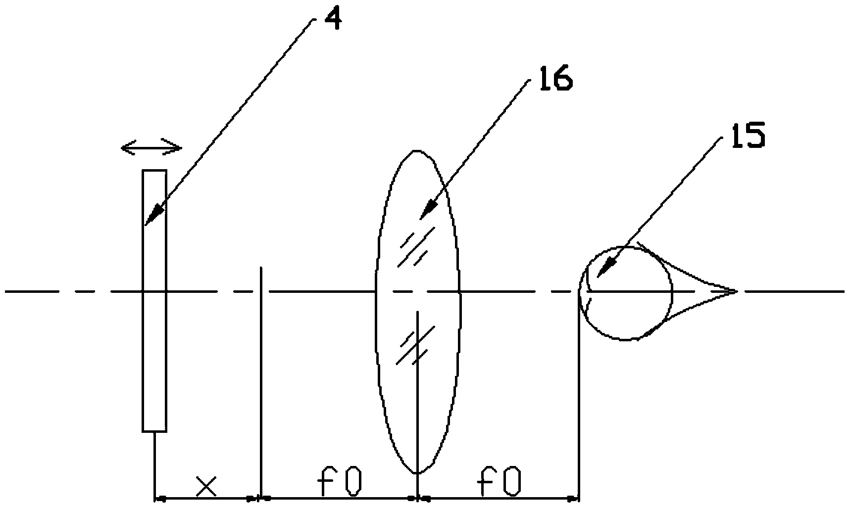
[0084] refer to figure 1 , figure 1It is a schematic diagram of the optical path structure of the present invention, including: an imaging lens group 16 and an eye chart 4. The cornea 15 of the human eye under test is located at the focal point on one side of the imaging lens group 16, and the center of the eye chart 4 is arranged on the other side of the imaging lens group 16. side and can move back and forth along the optical path. The purpose of setting the cornea 15 of the human eye under test at the focal point on one side of the imaging lens group 16 is to achieve a linear scale of diopter. According to the formula D1=x / (f0*f0), where D1 is the degree of refractive error of the human eye. x is the distance away from the focal length f0 of the imaging lens group 16 ...

Embodiment 2

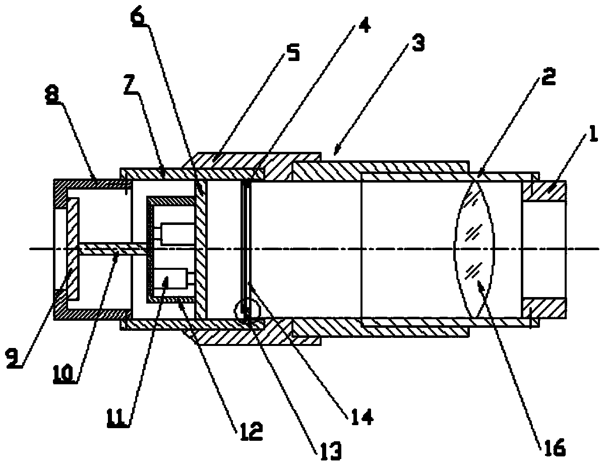
[0096] Different from Embodiment 1, the human cornea is not required to be located at the focal point on one side of the imaging lens group. In this case, the diopter scale on the adjustment knob 5 is not linear, but Embodiment 1 can also be realized. All the functions of the hand-held vision detection device mentioned above.

[0097] The invention also discloses a vision detection function and a specific operation method that can be realized by using the hand-held vision detection device.

[0098] For easy understanding, please refer to Figure 4 with Image 6 ,It should be noted, Image 6 The E vision chart in the chart complies with international standards. The vision chart can be C vision chart or other vision charts. The visual acuity value of the vision chart and the corresponding optotype can be replaced or increased or decreased under the premise of meeting international standards.

[0099] 1. Measurement of uncorrected visual acuity

[0100] refer to Figure 4 wi...


PUM


Abstract

The invention discloses a handheld vision detecting device which at least comprises an imaging lens set and a vision chart, wherein the imaging lens set is composed of at least one imaging lens. The cornea of a detected person can be located at the position of the focus on one side of the imaging lens set, the center of the vision chart is arranged on the other side of the imaging lens set, and the vision chart can move in a front-and-back mode along a light path. The invention further discloses a vision detecting method and the steps which can measure various visions with the handheld vision detecting device without wearing glasses. By means of the device, the functions that the naked eye vision is measured, the corrected vision is measured, the worn-glass degree are measured when the corrected vision achieves 1.0, the low vision and the weak vision are detected, and the astigmatism is detected can be achieved. By means of the handheld vision detecting device and the vision detecting method, users can detect the vision at any time and any place, the detecting results are accurate, and the operation is conveniently and easily achieved.

Description

technical field [0001] The invention relates to the technical field of optometry instruments, in particular to a vision testing device and a method for using the vision testing equipment to perform vision testing. Background technique [0002] At present, most of the eye charts used for testing eyesight on the market are printed eye charts. Although there are many forms of this kind of eye chart, the practical eye chart must be in a fixed place, a large space and an environment with standard eye chart brightness. , before the vision test can be performed. From the perspective of the subject of visual acuity testing, when people feel that there may be a problem with their vision, they will do the testing. The consequences of this passive testing often bring unpleasant effects to health and life. If the change from passive detection to active detection, from an objective and necessary detection environment to self-testing everywhere, it will provide a great guarantee for peop...

Claims


Application Information

Patent Timeline
Patent Type & Authority Applications(China)
IPC IPC(8): A61B3/036
CPCA61B3/032A61B3/0008A61B3/0075A61B3/036A61B2560/0431
Inventor 王辉甄毅郭曙光何卫红栾盾李鹏
Owner SHENZHEN CERTAINN TECH CO LTD
Why Eureka
Try Eureka