Automatic oil spraying device and method

An oil spraying device and automatic technology, which is applied in the direction of spraying devices, liquid spraying devices, and devices for coating liquid on the surface, etc., can solve the problems of not adopting sealing and isolation measures, only fixed-point spraying, and uneven spraying effect, etc., to achieve Improve the risk of personnel operation, prevent inhalation injury, and solve the effect of occupational injury

Active Publication Date: 2014-03-26
GUANGZHOU AUTOMIBILE GRP MOTOR
View PDF9 Cites 13 Cited by
  • Summary
  • Abstract
  • Description
  • Claims
  • Application Information

AI Technical Summary

Problems solved by technology

The Chinese utility model patent with the application number "03233557.1" discloses a motorcycle anti-rust oil spraying device, including oil spraying room, photoelectric side detector, electrical control box, spray gun and other structures. Anti-rust oil is automatically sprayed, but the oil spray room does not adopt sealing and isolation measures, and the workers are in direct contact with the spray, which is likely to cause occupational injuries; moreover, there is no recycling of excess oil or waste oil that cannot be fully utilized due to spraying. It is easy to cause environmental pollution and is not environmentally friendly
[0003] Therefore, the existing spraying technology has the following defects: (1) During the spraying process, the operators participate in the whole process on site and are in direct contact with the spray, so that the operators inhale a large amount of oil mist, which is prone to occupational injury; at the same time, the spraying process can only be sprayed at fixed points, It cannot be sprayed in large quantities, and the efficiency is low; (2) It is impossible to realize the automatic spraying of the overlapping parts of the overlapping boards independently; (3) After spraying, the trolley storing the boards has oil mist attached, which is prone to drip pollution after accumulation ; (4) When spraying a large number of panels at a time, special tooling is required to clamp the panels. The tooling is directly exposed to the oil mist environment, and oil mist adhesion cannot be avoided, which will affect the use of the tooling; (5) The existing spray The oil room can only be fixed at one location and cannot be moved according to the actual situation. It has disadvantages such as inconvenient use and inconvenient disassembly and assembly; (6) The existing spraying operation does not purify and recycle the waste oil, which easily causes environmental pollution and does not Environmental protection; (7) Artificial spraying is used, the oil is not easy to control, it is easy to cause oil waste, the oil loss is large, and the spraying effect is uneven, and the anti-rust effect is poor

Method used


Image

  • Automatic oil spraying device and method
  • Automatic oil spraying device and method
  • Automatic oil spraying device and method

Examples


Embodiment 1

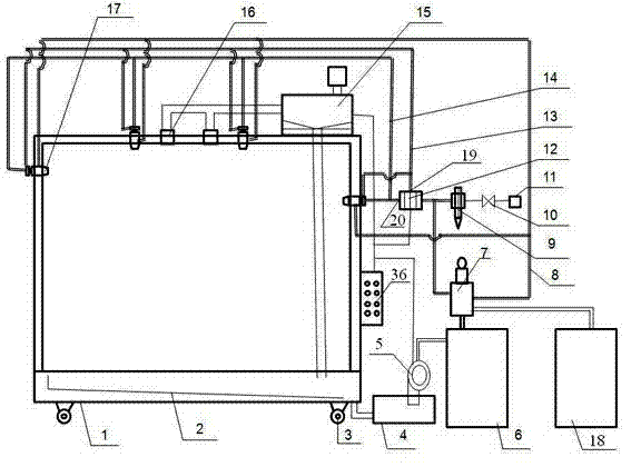
[0063] see Figure 1 to Figure 5 , the automatic fuel injection device includes a closed fuel injection room 1, a spray system, an oil recovery system and a control system 36. In the spray valve 17 on the airtight spray room 1, the main gas source 11 is connected with the pressurization mechanism 7, and the oil drum 18, the pressurization mechanism 7, and the spray valve 17 are connected through the oil pipe 8 in sequence; the solenoid valve 12 It includes an air inlet connected to the main gas source 11 through a pipeline, a first gas outlet 19 connected to each spray valve 17 through a driving gas source pipeline 13, and a first gas outlet 19 connected to each spray valve 17 through an atomizing gas source pipeline 14. The second air outlet 20; the driving gas source pipeline 13 is provided with a first pressure regulating mechanism, and the atomizing gas source pipeline 14 is provided with a second pressure regulating mechanism; the solenoid valve 12, oil recovery system A...

Embodiment 2

[0102] This embodiment is the same as Embodiment 1 except for the following features: the oil-water separation barrel is connected to the oil barrel through a pipeline, and an oil pump is also connected to the pipeline between the oil-water separation barrel and the oil barrel. In this way, the separated oil in the oil-water separation barrel can be pumped into the oil barrel by the oil pump, and the oil barrel can be reused through the spray system to form a loop for recycling.

Embodiment 3

[0104] This embodiment is the same as Embodiment 1 except for the following features: in the step (1) of the automatic oil injection method, the set pressure value of the oil pressure is 1Mpa, and the set drive pressure value is 0.3MPa, the set atomization pressure value is 0.1Mpa.


PUM


Abstract

The invention discloses an automatic oil spraying device which comprises a closed oil spraying room, a fog spraying system, an oil recycling system and a control system. The fog spraying system comprises a main air source, a pressurizing mechanism, an oil drum, an electromagnetic valve and fog spraying valves, wherein the main air source is connected with the pressurizing mechanism, and the oil drum, the pressurizing mechanism and the fog spraying valves are sequentially connected through oil pipes. The electromagnetic valve comprises an air inlet, a first air outlet and a second air outlet, wherein the air inlet is connected with the main air source through a pipe, the first air outlet is connected with the fog spraying valves through a driving air source pipe, and the second air outlet is connected with the fog spraying valves through an atomization air source pipe. The driving air source pipe and the atomization air source pipe are provided with a first pressure adjustment mechanism and a second pressure adjustment mechanism respectively. The electromagnetic valve and the oil recycling system are respectively connected with the control system, and the oil recycling system is connected with the closed oil spraying room. The invention further discloses an automatic oil spraying method achieved through the automatic oil spraying device. By means of the automatic oil spraying device and the automatic oil spraying method, rapid and safe rust prevention processing on a large number of plates can be achieved, operation risks to persons are reduced, and waste oil can be recycled.

Description

technical field [0001] The invention relates to an oil spraying device, in particular to an automatic oil spraying device and an automatic oil spraying method for spraying anti-rust oil on a stamping plate. Background technique [0002] At present, in the field of stamping, in order to avoid corrosion in large quantities of stock plates, anti-rust is often achieved by manual spraying of anti-rust oil. The tools are often a simple combination of oil barrels, pneumatic pumps and hand spray guns. The Chinese utility model patent with the application number "03233557.1" discloses a motorcycle anti-rust oil spraying device, including oil spraying room, photoelectric side detector, electrical control box, spray gun and other structures. Anti-rust oil is automatically sprayed, but the oil spray room does not adopt sealing and isolation measures, and the workers are in direct contact with the spray, which is likely to cause occupational injuries; moreover, there is no recycling of e...

Claims


Application Information

Patent Timeline
Patent Type & Authority Applications(China)
IPC IPC(8): B05B15/12B05B15/04B05B15/00B05B9/04B05D1/02
CPCB05B13/0278B05B14/43B05B14/49B05B16/40Y02P70/10
Inventor 钟剑谢卫林廖端马朋超胡奎刘在峰
Owner GUANGZHOU AUTOMIBILE GRP MOTOR
Why Eureka
Try Eureka