
A steam cleaning device for mixing tank of sintering machine

A cleaning device and mixing technology, applied in descaling devices, cleaning methods and utensils, cleaning methods using liquids, etc., can solve problems such as clogging, achieve good results, reduce excess wet belts, and improve sintered air permeability.

Active Publication Date: 2016-02-10
XINYU IRON & STEEL CO LTD
View PDF7 Cites 0 Cited by
  • Summary
  • Abstract
  • Description
  • Claims
  • Application Information

AI Technical Summary

Problems solved by technology

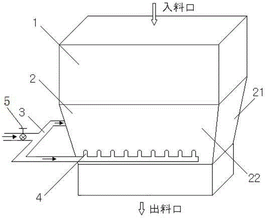
[0003] The technical problem to be solved by the present invention is to provide a steam anti-caking and anti-clogging device suitable for the characteristics of the sintering mixture tank, and can effectively remove the caking produced on the narrow side walls of the mixing tank. By adjusting the steam injection Point and increase the pressure of steam sprayed into the mixing tank to effectively solve the problem of material clogging in the mixing tank

Method used


Image

  • A steam cleaning device for mixing tank of sintering machine
  • A steam cleaning device for mixing tank of sintering machine
  • A steam cleaning device for mixing tank of sintering machine

Examples


Embodiment

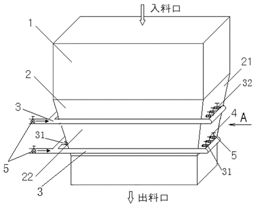
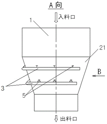
[0020] Embodiment: A steam cleaning device for the mixing tank of a sintering machine. Above the mixing tank 1 is a shuttle distributor that continuously feeds materials to the top of the mixing tank 1. Below it is the inclined bucket tank 2. The feeder discharges the mixed material from the outlet to the sintering machine trolley. Such as figure 2 , image 3 , the inclined bucket groove 2 below the mixing tank 1 is equipped with two upper and lower steam pipes 3 respectively, and the upper and lower steam pipes 3 are respectively equipped with three upper jets in the direction of the narrow inclined side wall 21. pipe 32 and three lower nozzle pipes 31. The upper and lower rows of spray pipes 32 and 31 are all connected to the steam nozzle 4 through the steam gate valve 5 . Such as Figure 4 , the lower nozzle pipe 31 is installed horizontally, and the upper nozzle pipe 32 is installed at an angle of 0° or 60° downward to the horizontal line, preferably at an angle of 40...


PUM


Abstract

The invention discloses a steam cleaner for a mixture trough of a sintering machine. According to the steam cleaner for the mixture trough of the sintering machine, an oblique hopper trough is connected to the bottom of the mixture trough and is composed of wide-surface oblique lateral walls and narrow-surface oblique lateral walls. Each narrow-surface oblique lateral wall is provided with an upper steam pipe and a lower steam pipe, wherein the upper steam pipe and the lower steam pipe are provided with an upper row of spray pipe and a lower row of spray pipe respectively and correspondingly, the upper row of spray pipe and the lower row of spray pipe are connected with steam spray heads respectively through steam gate valves, spray nozzle holes are formed in the narrow-surface oblique lateral wall, and the steam spray heads penetrate through the spray nozzle holes to the interior of the narrow-surface oblique lateral wall and are fixedly connected with the spray nozzle holes. According to the steam cleaner for the mixture trough of the sintering machine, the two rows of steam spray heads are arranged on each of the two narrow-surface oblique lateral walls of the mixture trough to clean the narrow-surface oblique lateral walls of the mixture trough and prevent material caking and blocking, and the problems of material adhesion, material hanging and material blocking in the mixture trough caused by the fact that the mobility of mixtures on the two narrow-surface areas of the mixture trough is poor and the mixtures can adhere to the two narrow-surface oblique lateral walls of the mixture trough easily when the viscidity of the mixtures is large are solved.

Description

technical field [0001] The invention relates to a cleaning device for a mixing tank of a sintering machine, which is used to prevent the mixing tank from clogging and clogging, in particular to a steam cleaning device for a mixing tank of a sintering machine. Background technique [0002] At present, in order to survive, the iron and steel industry mostly adopts a low-cost strategy to economically make iron. Sintering production uses low-cost and low-quality raw materials as much as possible. Such raw materials bring in more impurities, fine particle size, and high viscosity. Especially, the higher the proportion of limonite is used, the greater the viscosity of this type of mixture. Due to the small flow of material in the area of ​​the inclined side wall of the narrow side of the mixing trough, the material is easy to squeeze and adhere to the inclined wall of the trough, and the material flow at the junction of the wide and narrow sides of the trough is poor, and it is ea...

Claims


Application Information

Patent Timeline
Patent Type & Authority Patents(China)
IPC IPC(8): B08B3/02
CPCB08B3/02F27D25/008
Inventor 陈伍烈刘铁张思平聂绍昌刘定中罗来清周鹏飞周毅张武钢邹苏华
Owner XINYU IRON & STEEL CO LTD
Learn More