Crude oil coagulated pipe plug removal device and plug removal method with plug removal device

A technology of pipeline condenser and block remover, which is applied in chemical instruments and methods, cleaning methods and utensils, cleaning hollow objects, etc., can solve the problems of complicated blocking removal process, long construction time, structural damage of oil pipelines, etc. The blocking process is simple, the construction time is short, and the risk of environmental pollution is small.

Inactive Publication Date: 2014-03-26
蒋文明
View PDF7 Cites 7 Cited by
  • Summary
  • Abstract
  • Description
  • Claims
  • Application Information

AI Technical Summary

Problems solved by technology

[0004] The present invention solves the problem of easy leakage of oil in the existing blocking removal technology, causing environmental pollution, and causing structural damage to the oil pipeline. The blocking removal process is complicated and requires a lot of manpower, material and financial resources. In order to solve the problem of aggravated losses, and then provide a crude oil pipeline coagulation pipe unblocking device and a deblocking method using the deblocking device

Method used


Image

  • Crude oil coagulated pipe plug removal device and plug removal method with plug removal device
  • Crude oil coagulated pipe plug removal device and plug removal method with plug removal device

Examples


specific Embodiment approach 1

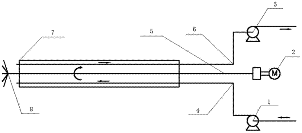
[0031] Specific Embodiment 1: A crude oil pipeline coagulation pipe unblocking device in this embodiment includes a liquid injection pump 1, a motor 2, a liquid suction pump 3, a casing 7, a liquid inlet pipe 4, a liquid outlet pipe 6, and an agitator drive shaft 5 and the agitator stirring head 8, the liquid inlet pipe 4, the liquid outlet pipe 6 and the agitator drive shaft 5 are set in the casing 7, the liquid inlet pipe 4 is connected with the injection pump 1, and the agitator transmission The shaft 5 is connected with the motor 2 , the liquid outlet pipe 6 is connected with the pump 3 , and the drive shaft 5 of the agitator is connected with the stirring head 8 of the agitator.

[0032] Further: the infusion pump 1 is made of stainless steel.

[0033] Further: the casing 7 is made of a rubber hose reinforced with stainless steel wire.

[0034] Further: The liquid inlet pipe 4 is made of a rubber hose reinforced with stainless steel wire.

[0035] Further: Motor 2 adopt...

specific Embodiment approach 2

[0040] Specific implementation mode two: the specific steps of the crude oil pipeline coagulation tube deblocking method of the present embodiment are:

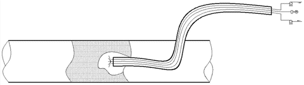
[0041] Step 1: Determine the position of the condensation pipe section and determine the available openings near the pipe;

[0042] Step 2: Insert the casing 7 of the plug remover into the available opening, so that the stirring head 8 of the agitator touches the solidified crude oil;

[0043] Step 3: Turn on the motor 2, drive the agitator transmission shaft 5, drive the agitator stirring head 8, and crush the solidified crude oil;

[0044] Step 4: Prepare the blocking solution, turn on the injection pump 1, pour the blocking solution into the solidified crude oil section through the liquid inlet pipe 4, and use the blocking solution to heat the solidified crude oil and broken particles;

[0045] Step 5: Turn on the liquid suction pump 3, and pump out the mixed liquid formed by the deblocking liquid after heat exchange and ...


PUM


Abstract

The invention relates to a pipe plug removal device and a plug removal method, in particular to a crude oil coagulated pipe plug removal device and a plug removal method with the plug removal device. The problems that existing pipe coagulated pipe plug removal is high in cost, and environmental pollution is easily caused are solved. The crude oil coagulated pipe plug removal device is characterized in that a liquid inlet pipe, a liquid outlet pipe and a stirrer transmission shaft are installed in a sleeve in a sleeved mode, the liquid inlet pipe is connected with a liquid injection pump, the stirrer transmission shaft is connected with a motor, the liquid outlet pipe is connected with a liquid infusion pump, and the stirrer transmission shaft is connected with a stirring head of a stirrer. The plug removal method includes the steps of judging the position of a coagulated pipe section, determining an available opening of the pipe, inserting the sleeve into the available opening, and enabling the stirring head to be in contact with coagulated crude oil; starting the motor to drive the transmission shaft to drive the stirring head to crash the coagulated crude oil; starting the liquid injection pump to pump plug removal liquid into the coagulated crude oil section; starting the liquid infusion pump to pump out mixing liquid; when plug removal is finished, shutting down the liquid injection pump and the motor, then shutting down the liquid infusion pump, pulling out the sleeve, recovering the original appearance of the pipe, and finishing plug removal. The device and method are used for crude oil coagulated pipe plug removal.

Description

technical field [0001] The invention relates to a pipeline block removing device and a blocking removing method, in particular to a crude oil pipeline coagulation pipe blocking removing device and a blocking removing method using the blocking removing device, and belongs to the technical field of crude oil transportation. Background technique [0002] During the transportation of crude oil, the temperature of the oil in the pipeline will gradually decrease. When the temperature is lower than the wax precipitation point of crude oil, the wax dissolved in the crude oil will gradually precipitate out to form solid paraffin crystals, and some of the paraffin crystals will adhere to the inner wall of the pipeline. , forming paraffin crystal centers. As the temperature continues to decrease, the paraffin crystals on the pipe wall begin to grow, forming a wax layer with uneven thickness, resulting in a gradual decrease in the inner diameter of the pipe. When the temperature of cru...

Claims


Application Information

Patent Timeline
Patent Type & Authority Applications(China)
IPC IPC(8): B08B9/027
CPCB08B9/027
Inventor 蒋文明
Owner 蒋文明
Why Eureka
Try Eureka