
Vehicle and control method

A control method and vehicle technology, applied in the field of vehicles, to achieve the effect of suppressing the deterioration of drivability

Inactive Publication Date: 2014-03-26
TOYOTA JIDOSHA KK
View PDF7 Cites 6 Cited by
  • Summary
  • Abstract
  • Description
  • Claims
  • Application Information

AI Technical Summary

Problems solved by technology

The issue is not yet known to the public

Method used


Image

  • Vehicle and control method
  • Vehicle and control method
  • Vehicle and control method

Examples


Embodiment Construction

[0018] An embodiment of the present invention will be described in detail with reference to the accompanying drawings.

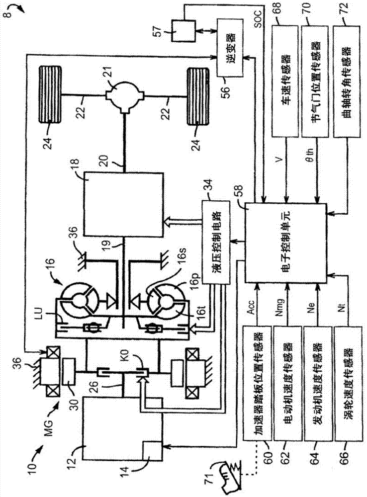
[0019] figure 1 The configuration of a drive system of a hybrid vehicle 8 (which will also be simply referred to as "vehicle 8") as one embodiment of the present invention is schematically shown. The hybrid vehicle 8 includes a vehicle powertrain 10 (will be referred to as "powertrain 10"), a differential gear unit 21, a pair of left and right axles 22, a pair of left and right drive wheels 24, a hydraulic control circuit 34, an inverter (inverter) 56 and electronic control unit 58. The power train 10 includes: an engine 12 used as a driving power source for vehicle operation; an engine output control unit 14 which performs engine output control such as starting or stopping of the engine 12, or throttle control; an electric motor for vehicle operation MG, which is used as a driving power source for vehicle operation; an engine coupling / disengagement clutch...


PUM


Abstract

The invention provides a vehicle and a control method. When an engine (12) is started in a motor running mode, a control unit performs engine starting control by raising the engine speed through slip engagement of an engine coupling / decoupling clutch (KO), temporarily reducing engaging force of the engine coupling / decoupling clutch after the engine (12) becomes able to rotate by itself, and then fully engaging the engine coupling / decoupling clutch (KO). The control unit advances the intake valve opening / closing timing at an earlier point in time as the motor speed is higher.

Description

technical field [0001] The present invention relates to a vehicle in which engine start control is performed when an engine is started while the vehicle is running on power of an electric motor, and also relates to a control method for the vehicle. Background technique [0002] A vehicle is known that includes an engine, an electric motor, and an engine clutch that selectively couples the engine to a power transmission line from the electric motor to drive wheels. A control system for this type of vehicle is disclosed in, for example, Japanese Patent Application Publication No. 2011-016390 (JP2011-016390A). The control system for the vehicle disclosed in JP2011-016390A, when starting the engine while the vehicle is running on the power of the electric motor alone, performs engine start control to temporarily release the engine during the period from when the engine clutch starts to be engaged to when it is fully engaged clutch. More specifically, under engine start control...

Claims


Application Information

Patent Timeline
Patent Type & Authority Applications(China)
IPC IPC(8): B60W30/18B60W10/06B60W10/08B60W10/02
CPCB60W10/02B60W10/06B60W10/08B60W20/40B60W30/18B60W2510/083B60W2510/0614B60W2510/0638B60W2710/081B60W2710/0616B60W2710/025B60W2540/10B60W2520/10B60W2510/244B60K6/48B60W2510/081B60W2710/023B60W2710/0605B60W2710/0644Y10S903/902Y02T10/62
Inventor 仲西直器松谷慎太郎
Owner TOYOTA JIDOSHA KK
Learn More