
Rotary unloading type air lock controllable unloading machine

A technology of unloading machine and unloading mechanism, which is applied in the direction of loading/unloading, transportation and packaging, and can solve the problems of accurately controlling the state of material distribution

Inactive Publication Date: 2015-12-09
HUANGGANG WEISI MACHINERY
View PDF5 Cites 0 Cited by
  • Summary
  • Abstract
  • Description
  • Claims
  • Application Information

AI Technical Summary

Problems solved by technology

[0002] As we all know, during the production and processing of powder and slag materials, it is usually necessary to quantify the materials before transporting them to the processing or packaging institutions, and the automatic material distribution and unloading process has always been a difficult problem in automated production; in the coal mining industry For example, coal powder is usually placed in the hopper, and the lower part of the hopper is connected with a scraper conveyor. In the prior art, the gravity of the coal powder is usually directly used to control the discharge opening of the hopper. In this way, the material unloading speed and the accuracy of material distribution are affected by many aspects such as the material stock in the hopper, the diameter of the material powder, the dry humidity of the material, etc., and it is difficult to achieve accurate Control the dispensing status of materials

Method used


Image

  • Rotary unloading type air lock controllable unloading machine
  • Rotary unloading type air lock controllable unloading machine
  • Rotary unloading type air lock controllable unloading machine

Examples


Embodiment Construction

[0020] The specific implementation manners of the present invention will be further described in detail below in conjunction with the accompanying drawings and embodiments. The following examples are used to illustrate the present invention, but are not intended to limit the scope of the present invention.

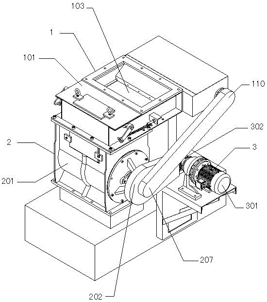
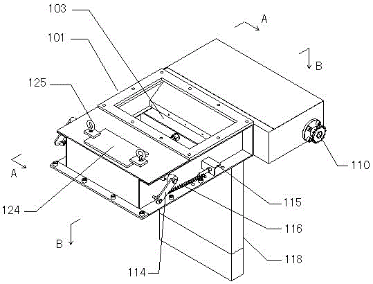
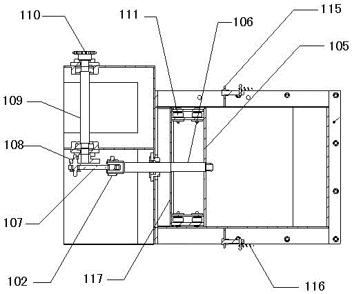
[0021] Such as Figure 1 to Figure 6 As shown, the rotary unloading type air-lock controllable unloading machine of the present invention includes a material distribution mechanism 1, a material discharge mechanism 2 and a power mechanism 3; the material distribution mechanism includes a material distribution box 101 and a pushing device 102, and the material distribution mechanism The top of one side of the box body is provided with a material inlet 103, and the bottom of the other side of the material distribution box is provided with a material discharge port 104. The pushing device includes a front push plate 105, a push rod 106, a connecting rod 107, an eccentric whee...


PUM


Abstract

The invention discloses a material separation loading and unloading device, and particularly relates to a rotating-unloading-type air-lock controllable unloading machine which can effectively and accurately achieve and control material separation and unloading states. The rotating-unloading-type air-lock controllable unloading machine comprises a separation mechanism, an unloading mechanism and a power mechanism. The separation mechanism comprises a separation box and a pushing device; a feeding port is formed in the top of one side of the separation box, and a discharging port is formed in the bottom of the other side of the separation box; the pushing device comprises a front push plate, a push rod, a connecting rod, an eccentric wheel, a crankshaft and a first chain wheel, wherein the front push plate, the push rod, the connecting rod, the eccentric wheel, the crankshaft and the first chain wheel are mutually connected, and rollers are arranged at the two ends of the back side of the front push plate. The unloading mechanism comprises an unloading box, a second chain wheel, a main shaft and impeller blades, wherein a receiving port is formed in the top of the unloading box, an outlet is formed in the bottom of the unloading box, the receiving port is connected to the bottom of the discharging port, the second chain wheel is fixed to the end of the main shaft and is in transmission connection with the power mechanism, and the impeller blades are symmetrically and fixedly arranged on the main shaft.

Description

technical field [0001] The invention relates to the technical field of material loading and unloading devices, in particular to a rotary unloading type air-locking controllable unloading machine. Background technique [0002] As we all know, during the production and processing of powder and slag materials, it is usually necessary to quantify the materials before transporting them to the processing or packaging institutions, and the automatic material distribution and unloading process has always been a difficult problem in automated production; in the coal mining industry For example, coal powder is usually placed in the hopper, and the lower part of the hopper is connected with a scraper conveyor. In the prior art, the gravity of the coal powder is usually directly used to control the discharge opening of the hopper. In this way, the material unloading speed and the accuracy of material distribution are affected by many aspects such as the material stock in the hopper, the...

Claims


Application Information

Patent Timeline
Patent Type & Authority Patents(China)
IPC IPC(8): B65G65/48B65G65/40B65G69/00
Inventor 谢梓操
Owner HUANGGANG WEISI MACHINERY
Learn More