
Safe releasing tool for horizontal well

A technology for throwing away tools and horizontal wells, which is applied in wellbore/well parts, earthwork drilling and production, etc. It can solve problems such as unreasonable structure, low work efficiency, cumbersome installation and use, etc., and achieve reasonable structural design, saving production costs, The effect of low cost of use

Inactive Publication Date: 2014-03-26
YANCHENG SENXIN PETROLEUM MACHINERY
View PDF0 Cites 0 Cited by
  • Summary
  • Abstract
  • Description
  • Claims
  • Application Information

AI Technical Summary

Problems solved by technology

[0002] The oilfield has entered the later stage of development, the number of difficult-to-recover blocks has increased, the water injection pressure is high, and the downhole string technology for layered water injection and layered squeeze injection is relatively complicated, which seriously affects the normal production of the oilfield
With the development of mechanical water plugging technology, the drop-off joint of the ball throwing type and the drop-off type of the reverse buckle can no longer fully meet the construction requirements, and the drop-off of the ball-dropping pressure-suppressing method is easy to occur when it is applied in highly inclined directional wells and horizontal wells. The steel ball cannot be sealed in place, so that it cannot be dropped. Although the current technology solves the above problems to a certain extent, due to its unreasonable structure, it causes cumbersome installation and use, and low work efficiency. It may even cause oil and water well overhaul operations. To solve such problems, the hidden danger of accidents must be completely eliminated from the structural design of lost tools.
Moreover, some completion pipe strings cannot be reversed and lost due to reasons such as not allowing rotation, which has brought great trouble to the construction.

Method used


Image

  • Safe releasing tool for horizontal well

Examples


Embodiment Construction

[0012] The present invention will be further described below in conjunction with the accompanying drawings.

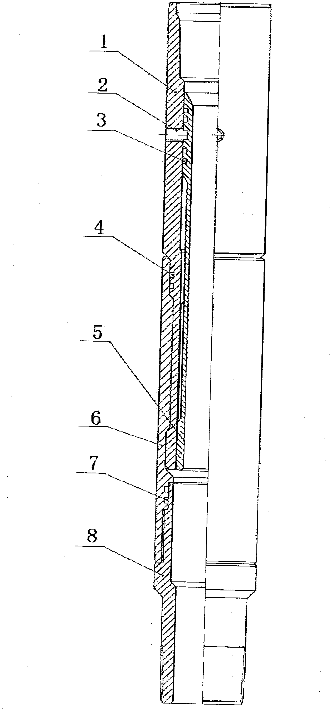
[0013] A safe hands-free tool for horizontal wells, comprising an upper joint 1, shear nails 2, a seal ring 3, a seal ring A4, a hands-free sliding sleeve 5, a seal sleeve 6, a seal ring C7, and a lower joint 8, and is characterized in that The sealing ring C7 is embedded in the sealing groove of the sealing sleeve 6, and then connected with the lower joint 8 through threads and tightened; the sealing ring A4 is embedded in the sealing groove of the upper joint 1, and the sealing ring 3 is embedded in the sliding sleeve 5; install the lower end of the upper joint 1 into the inner groove of the sealing sleeve 6, and install the sliding sleeve 5 of the upper sealing ring 3 into the inner hole of the upper joint 1, so that the upper joint 1 The lower end is just pressed into the inner groove of the sealing sleeve 6 . Install the scissors 2 into the scissors grooves of th...


PUM


Abstract

A safe releasing tool for a horizontal well comprises an upper connector, a shear pin, sealing rings, sealing rings A, a releasing sliding sleeve, a sealing sleeve, sealing rings C and a lower connector. The safe releasing tool for the horizontal well is characterized in that the sealing rings C are embedded into a sealing groove of the sealing sleeve and then the sealing rings C are connected and screwed with the lower connector through threads; the sealing rings A are embedded into a sealing groove of the upper connector; the sealing rings are embedded into a sealing groove of the releasing sliding sleeve; the lower end of the upper connector is installed inside an inner groove of the sealing sleeve; the releasing sliding sleeve which is screwed with the sealing rings is installed in an inner hole of the upper connector; so that the lower end portion of the upper connector is rightly pressed into the inner groove of the sealing sleeve and the shear pin is installed inside a shear pin groove of the releasing sliding sleeve through a threaded hole of the upper connector. Compared with the prior art, the safe releasing tool for the horizontal well has the advantages of guaranteeing reliability of releasing operating modes, being reasonable in structural design, enabling a device to be simple, being low in utilization cost and convenient to install and saving production costs of the device.

Description

technical field [0001] The invention belongs to oilfield equipment, and relates to the field of oilfield mechanical water shutoff, in particular to a safe hands-free tool for horizontal wells. Background technique [0002] As the oilfield enters the later stage of development, the number of hard-to-recover blocks increases, the water injection pressure is high, and the downhole string technology for layered water injection and layered squeeze injection is relatively complicated, which seriously affects the normal production of the oilfield. With the development of mechanical water plugging technology, the throwing ball type drop joint and the inverted buckle type drop joint can no longer fully meet the construction requirements, and the ball drop type is used to hold the pressure, which is easy to occur when it is used in highly inclined directional wells and horizontal wells. The steel ball cannot be sealed in place, so that it cannot be dropped. Although the current techno...

Claims


Application Information

Patent Timeline
IPC IPC(8): E21B23/00
Inventor 徐红军徐丰岭
Owner YANCHENG SENXIN PETROLEUM MACHINERY
Learn More