Vehicle vibration power generating device

A vibration power generation and vehicle technology, which is applied in the direction of electromechanical devices, electrical components, electric components, etc., can solve the problems of power lines affecting the cleanliness and beauty of the car, short battery life of portable electronic devices, and pollution in the use of batteries, so as to achieve energy transmission High efficiency, high power supply efficiency, and long working hours

Active Publication Date: 2014-03-26
HEBEI UNIV OF TECH
View PDF6 Cites 4 Cited by
  • Summary
  • Abstract
  • Description
  • Claims
  • Application Information

AI Technical Summary

Problems solved by technology

[0003] 1. The use of on-board power supply requires the output of electric energy by the car generator, which will increase the fuel consumption of the vehicle. In today's high oil price, it is obviously not economical and increases environmental pollution
[0004] 2. Portable electronic devices powered by batteries have a short battery life and need to carry charging equipment, and the use of batteries also causes pollution
[0005] 3. Many vehicle-mounted portable electronic devices are powered by USB power supply. The original vehicle power supply needs to be connected to an external power converter to convert the 12V cigarette lighter power supply to USB power supply. The secondary power supply efficiency is low and the cost is high.
[0006] 4. Messy power cords affect the cleanliness and beauty of the car

Method used


Image

  • Vehicle vibration power generating device
  • Vehicle vibration power generating device
  • Vehicle vibration power generating device

Examples


Embodiment 1

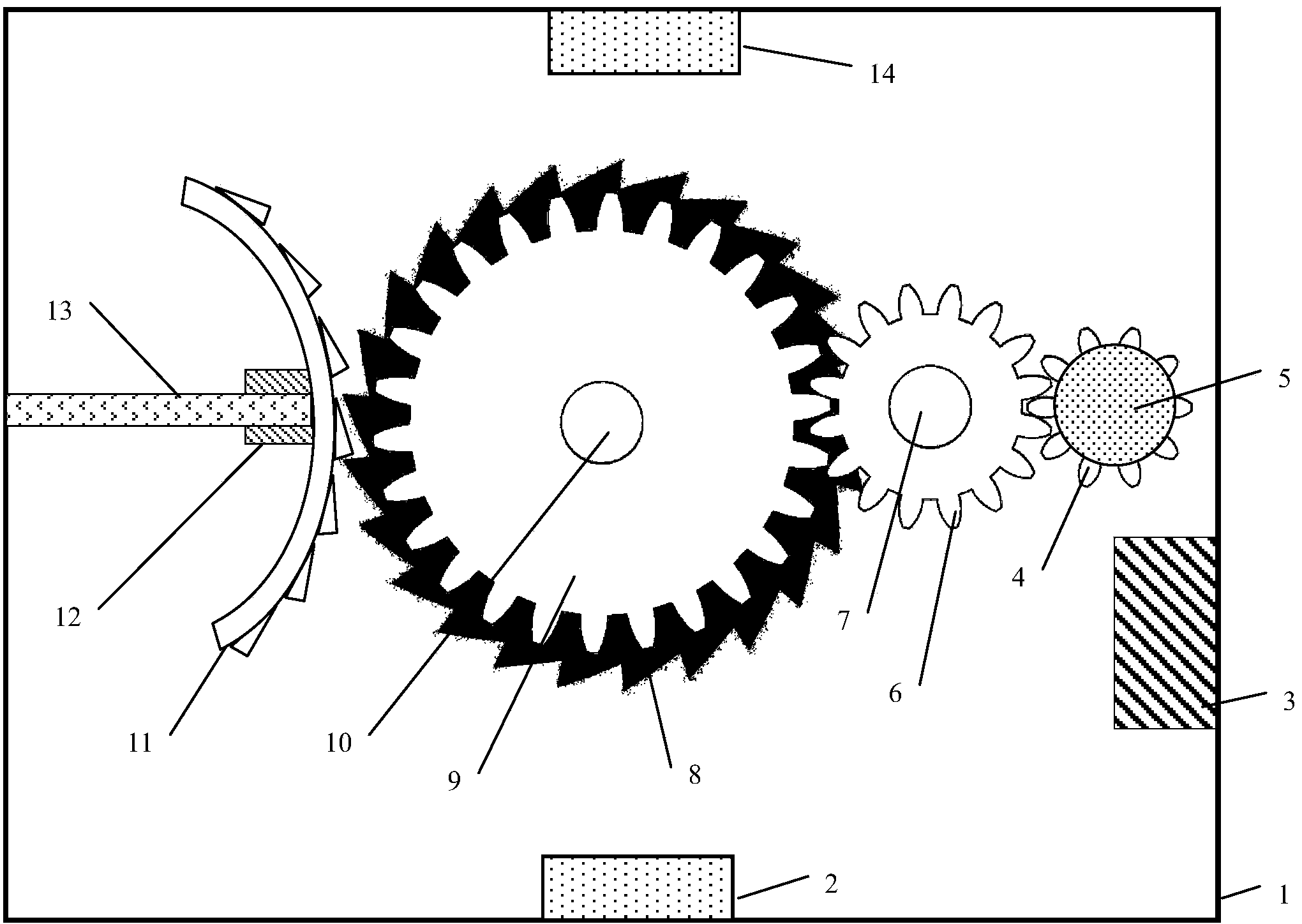
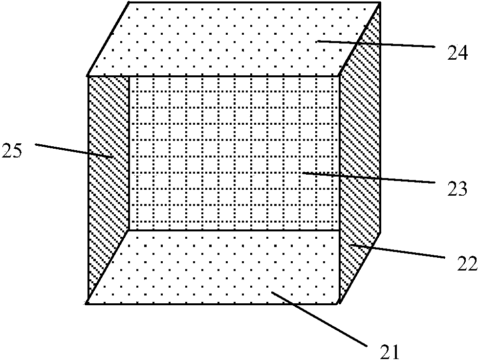
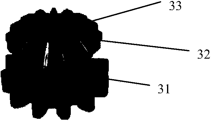
[0030] The structural diagram of the vibration power generation device of this vehicle is as follows: figure 1 As shown, the device is a box structure with a cubic shape; inside the box, a magnetic attraction 2 and a magnetic attraction 14 are respectively fixed on the top and bottom; the DC permanent magnet generator 5, shaft one 10, and shaft two 7 are all fixed on the On the inner wall of the same box bottom plate 23, the horizontal heights of the DC permanent magnet generator 5, shaft one 10, and shaft two 7 are the same or similar; the gear three 4 is fixed on the shaft of the DC permanent magnet generator 5 through interference fit , gear two 6 is fixed on the bearing of shaft two 7 through interference fit, gear one 9 and ratchet 8 are fixed on the one-way bearing of shaft one 10 through interference fit, wherein gear one 9 is riveted and fixed on ratchet 8, Coaxial rotation; at the same time, the third gear 4 and the second gear 6 are engaged together, and the second g...


PUM


Abstract

The invention relates to a vehicle vibration power generating device. The vehicle vibration power generating device adopts a cantilever beam and a ratchet wheel as a vibration picking mechanism, adopts a one-way bearing and a gear set as a vibration mechanical energy transmission mechanism and adopts a direct current permanent magnet generator as an electromechanical energy conversion mechanism, and an electric energy processing circuit with a USB interface processes irregular alternating electricity to supply electricity to vehicle-mounted electronic equipment. According to the vehicle vibration power generating device, the cantilever beam and ratchet wheel mechanism is used for pricking vibration, linear movement in the vertical direction in the running process of a vehicle is converted into rotary movement, an efficient one-way gear mechanism drives the low-damping permanent magnet direct current generator to work, and the transmission and conversion efficiency of vibration mechanical energy can be obviously improved compared with a common linear vibration power generating device. The vehicle vibration power generating device generates electricity with renewable energy sources, is high in vibration picking efficiency and energy transmission and conversion efficiency, is long in service life, adopts the USB interface, is suitable for most vehicle-mounted electronic equipment, and is high in universality.

Description

technical field [0001] The invention relates to the technology of converting the mechanical energy of vehicle vibration into electric energy, in particular to a cantilever beam and ratchet type vibration pickup mechanism, a one-way bearing and a one-way transmission mechanism of a gear set, a DC permanent magnet generator, an electric energy processing circuit device and its realization The method specifically adopts a cantilever beam, a load, an arc-shaped rack, a ratchet, a one-way bearing, a gear set, a DC permanent magnet generator, a power processing circuit with a USB interface, a magnetic attraction, and a casing to realize the vibration of the vehicle during driving. A device that converts mechanical energy into electrical energy. Background technique [0002] Vehicles are becoming more and more popular in life and production, and the applications of related portable electronic devices are also increasing, such as: car navigators, driving recorders, handheld electron...

Claims


Application Information

Patent Timeline
Patent Type & Authority Applications(China)
IPC IPC(8): F03G7/08H02K7/18H02K7/116
CPCF03G7/08
Inventor 王志华王莉王博文姚涛
Owner HEBEI UNIV OF TECH
Why Eureka
Try Eureka