
Novel pipeline connecting pressure-resisting flange and application

A flange and pipeline technology, applied in the field of pipeline connection design, can solve the problems of insufficient flange stiffness, warping deformation, neglect of compressive performance, short flange life, etc., to avoid distortion or damage, easy alignment, and simple structure. Effect

Inactive Publication Date: 2014-03-26
天津泉达农作物种植有限公司
View PDF0 Cites 3 Cited by
  • Summary
  • Abstract
  • Description
  • Claims
  • Application Information

AI Technical Summary

Problems solved by technology

However, insufficient flange stiffness often results in excessive warping deformation, which is often one of the main reasons for the failure of the bolted flange connection seal in actual production; butt welding flanges are not easy to deform, have good sealing, and are widely used, suitable for pressure or Pipelines with large temperature fluctuations or high-temperature, high-pressure and low-temperature pipelines are also used for pipelines that transport expensive, flammable and explosive media
Under the influence of strong pressure, the service life of many flanges is very short, about 10-15 years
At present, the research on the compressive performance of flanges focuses on the material and preparation process of the flange, but ignores the influence of its structural design on the compressive performance.

Method used


Image

  • Novel pipeline connecting pressure-resisting flange and application

Examples


Embodiment Construction

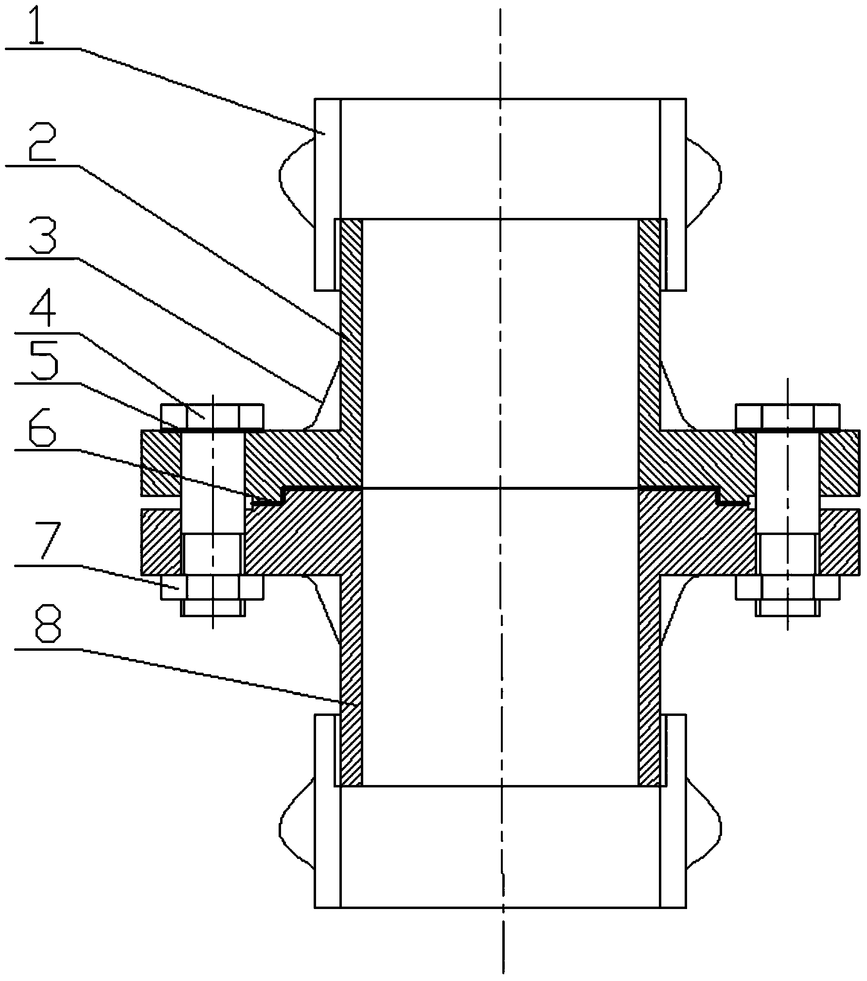
[0017] The present invention will be further described below in conjunction with the accompanying drawings. Such as figure 1 As shown, the inner diameter of the pressure-resistant pipe 1 is larger than the outer diameter of the flange connection pipe. After the pipe connection pipe is welded to the concave-convex flange, one end of the pressure-resistant pipe 1 is welded together with the pipe connection pipe, and the other end of the pressure-resistant pipe 1 is a threaded structure. The concave flange 2 and the convex flange 8 are threaded to make the connection between the flange and the pipeline tighter, and to prevent the risk of cracks at the connection between the flange and the pipeline caused by excessive internal pressure of the pipeline. A pair of concave and convex Face flange 28, middle dress flange gasket 6, connect with bolt 4, the nut 7 that bolt 4 matches with it is fixed together.

[0018] Finally, it should be noted that: the above embodiments are only used...


PUM


Abstract

The invention relates to a novel pipeline connecting pressure-resisting flange which comprises a pressure-resisting pipe, a concave face flange, a reinforcing rib, a bolt, a bolt gasket, a flange gasket, a nut and a convex face flange. A flange connecting pipe is arranged on a flange disk. The pressure-resisting pipe with the diameter larger than the diameter of a pipeline connecting pipe is arranged on the flange connecting pipe in a sleeved mode. One end of the pressure-resisting pipe is connected with the end of a concave face flange and convex face flange connecting pipe through threads. The other end of the pressure resisting pipe is connected with the pipeline connecting pipe in a welding mode, so that the connection between the flange and the pipeline connecting pipe is made to be firmer. The concave face flange and the convex face flange are adopted in a paired mode, so that the sealing performance is good, and centering is easy at installation time. The reinforcing rib is welded between the flange connecting pipe and the flange disk, so that flange rigidity is reinforced, and overlarge warping deformation caused by insufficient flange rigidity is avoided. The bolt is used for connection, pre-tightening force is provided to realize initial sealing, and axial force generated by internal pressure is borne, so that the structure can be detached, and utilization is convenient. The novel pipeline connecting pressure-resisting flange is reasonable in structure, easy to produce and manufacture, strong in pressure-resisting performance, large in rigidity, incapable of deforming easily, convenient to install, capable of centering easily, and good in sealing performance.

Description

[0001] The invention relates to a pipeline connection flange, in particular to a pipeline connection pressure-resistant flange, which belongs to the technical field of pipeline connection design. Background technique [0002] Flanges are also called flanges or flanges. Flanges are parts that connect pipes and pipes and valves to each other, and are connected to the pipe end. Flanges have been widely used in the field of pipeline connection and play a vital role. Flanges are generally used in pairs. A pair of flanges are provided with mounting holes corresponding to each other, and the pipes are well connected through the mounting holes through bolts and other connecting parts. The compression resistance of the flange is an important indicator to measure the quality of the flange, and it is also a guarantee to ensure the normal operation of the pipeline. However, insufficient flange stiffness often results in excessive warping deformation, which is often one of the main reason...

Claims


Application Information

Patent Timeline
IPC IPC(8): F16L23/032F16L57/02
CPCF16L23/032F16L57/02
Inventor 张伯泉
Owner 天津泉达农作物种植有限公司
Learn More