Natural heat dissipation energy-saving electric ceramic stove

A technology of natural heat dissipation and electric ceramic stove, which is applied in household heating, heating fuel, household stove/stove, etc. It can solve the problems of underutilization of heat energy, interference with life and work, and many safety hazards, so as to avoid heat energy Directly radiate the desktop, improve reliability and safety, and meet the effect of diverse shapes

Active Publication Date: 2015-11-18
胡曦文
View PDF10 Cites 0 Cited by
  • Summary
  • Abstract
  • Description
  • Claims
  • Application Information

AI Technical Summary

Problems solved by technology

[0003] 1. Noise, when the fan is working, the fan will generate a certain amount of noise, which will interfere with people's life and work;
[0004] 2. Uneven heat dissipation. When the heat is close to the place closest to the fan, the heat circulates quickly, but the heat accumulates and does not circulate in the place far away from the fan. If the heat accumulates and does not circulate for too long, the performance and function of the electrical appliance will be greatly reduced, which will cause safety hazards over time. Hidden danger;
[0005] 3. The efficiency is low, a large amount of heat is consumed by heat dissipation, and the heat energy is not fully utilized
[0006] 4. Low performance and many potential safety hazards. When the fan is used for heat dissipation, when the fan fails, the entire electrical cooling system will be paralyzed. After the cooling system is paralyzed, if the electrical appliance can still work, it will easily cause electrical fire or electric shock.
[0008] 6. Due to the limitation of heat dissipation conditions, most products are a rigid plane, lacking more practical and beautiful product shapes

Method used


Image

  • Natural heat dissipation energy-saving electric ceramic stove
  • Natural heat dissipation energy-saving electric ceramic stove
  • Natural heat dissipation energy-saving electric ceramic stove

Examples


Embodiment Construction

[0025] In order to make the object, technical solution and advantages of the present invention more clear, the present invention will be further described in detail below in conjunction with the accompanying drawings and embodiments. It should be understood that the specific embodiments described here are only used to explain the present invention, not to limit the present invention.

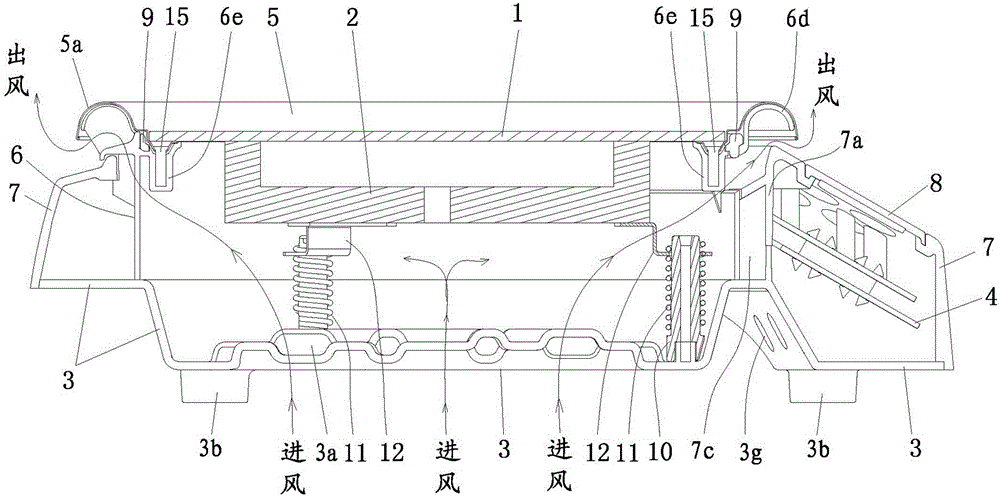
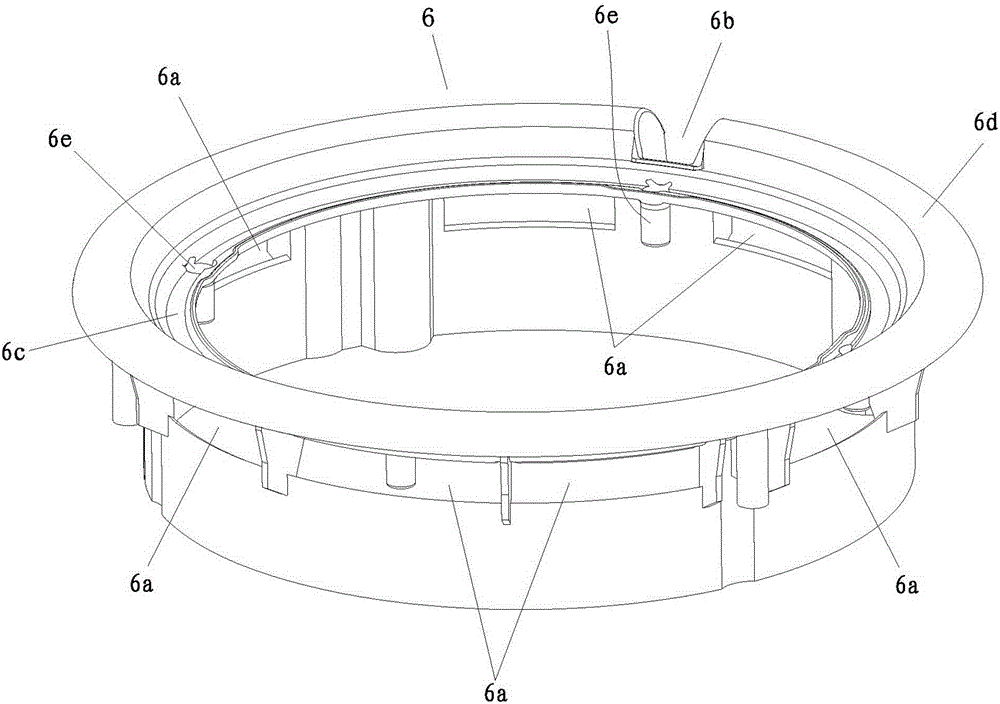
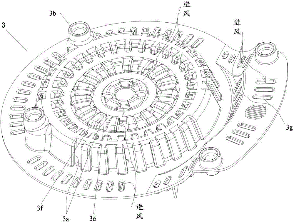
[0026] Such as figure 1 As shown, the natural heat dissipation energy-saving electric ceramic furnace at least includes: a microcrystalline plate 1 stacked from top to bottom, a furnace plate 2, a bracket device for supporting the furnace plate, and a bottom shell 3, and the furnace plate is electrically connected to a The control circuit board 4, the microcrystalline board is embedded in the decoration ring 5, the decoration ring is fixed on the top of the heat insulation sleeve 6, the bottom of the heat insulation sleeve is fixed on the bottom shell, and the heat insulation sleeve is placed on...


PUM


Abstract

The invention discloses a natural heat-dissipating energy-saving electric ceramic furnace, which mainly comprises a microcrystal plate (1), a furnace tray (2), a bracket device for supporting the furnace tray, and a bottom shell (3) arranged from top to bottom, wherein the furnace tray is electrically connected with a control circuit board (4); the microcrystal plate is embedded into a decorating ring (5); the decorating ring is fixed on the top of an insulating casing (6); the bottom of the insulating casing is fixed on the bottom shell; the insulating casing is arranged in a surface shell (7); the surface shell is covered on the bottom shell; the bottom shell is provided with a plurality of air inlets (3a); the insulating casing extends upwards out of the central port of the surface shell, and a side wall extending out of the surface shell is provided with a plurality of air outlets (6a); a three-dimensional upward heat-dissipating air duct is formed between the air inlets and the air outlets. No fan is used in the furnace, so that the fault rate and the electric energy consumption are reduced, and the noise is eliminated; a projecting fender design is adopted, so that various appearances can be formed, and a better heat-reserving effect is achieved.

Description

technical field [0001] The invention relates to an electric ceramic stove, in particular to a fanless natural heat dissipation energy-saving electric ceramic stove. Background technique [0002] Because of its high thermal efficiency, fast heating, and versatility, electric ceramic stoves are increasingly becoming popular kitchen utensils. Most of the existing electric ceramic stoves use fans for forced heat dissipation, and a few use metal shells for natural heat dissipation. The existing heat dissipation method has the following obvious defects: [0003] 1. Noise, when the fan is working, the fan will generate a certain amount of noise, which will interfere with people's life and work; [0004] 2. Uneven heat dissipation. When the heat is close to the place closest to the fan, the heat circulates quickly, but the heat accumulates and does not circulate in the place far away from the fan. If the heat accumulates and does not circulate for too long, the performance and fun...

Claims


Application Information

Patent Timeline
Patent Type & Authority Patents(China)
IPC IPC(8): F24C7/00
Inventor 胡岩张成伟
Owner 胡曦文
Why Eureka
Try Eureka