
Image correcting system for deformation measurement of speckle correlation methods

A technology for measuring images and speckle, which is applied to measuring devices, instruments, optical devices, etc., can solve the problems of non-perpendicular and reduce the accuracy and speed of speckle deformation measurement, and achieve the effect of improving reliability, sensitivity and speed.

Inactive Publication Date: 2014-03-26
CIVIL AVIATION UNIV OF CHINA
View PDF8 Cites 10 Cited by
  • Summary
  • Abstract
  • Description
  • Claims
  • Application Information

AI Technical Summary

Problems solved by technology

However, during the image acquisition process, it is difficult to precisely control the attitude of the camera and the speckle plane to be measured, so there is a certain distortion in the acquired image, which has great impact on the grid division, correlation calculation, search method, sub-pixel positioning and gray scale reconstruction of subsequent images. Now, etc. have a great influence, and even introduce huge measurement errors, thus reducing the accuracy and speed of speckle deformation measurement
In view of the above-mentioned problems in the deformation measurement process, how to overcome the influence caused by the non-perpendicularity of the optical axis of the CCD camera and the plane of the speckle object to be measured in the speckle deformation measurement, and how to quickly detect the three-dimensional coordinates of the feature points on the speckle image and Attitude information, how to correct the collected speckle images at the first time and then perform correlation calculations are all problems that need to be solved

Method used


Image

  • Image correcting system for deformation measurement of speckle correlation methods

Examples


Embodiment Construction

[0014] The speckle correlation method deformation measurement image correction system provided by the present invention will be described in detail below with reference to the accompanying drawings and specific embodiments.

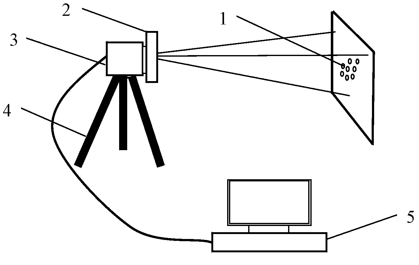
[0015] Such as figure 1 As shown, the speckle correlation method deformation measurement image correction system provided by the present invention includes: an external orientation marker 1, a light source 2, a CCD camera 3, a camera bracket 4, and an image data acquisition and processing device 5;

[0016] Among them: the external orientation mark 1 is placed in the middle of the speckle plane to be measured, and is used to measure the three-dimensional coordinates and attitude of the characteristic control points of the speckle plane to be measured, which helps the CCD camera 3 to quickly and accurately obtain the orientation mark information;

[0017] The light source 2 is installed on the front end of the lens of the CCD camera 3 and coaxial with it, ...


PUM


Abstract

An image correcting system for deformation measurement of speckle correlation methods is provided. The image correcting system comprises an outer direction mark, a light source, a CCD, a camera support and an image data acquiring and processing device. The outer direction mark is attached to the middle of the plane of a speckle to be measured, the light source is arranged at the front end of a lens of the CCD and is coaxial with the lens, and the CCD is fixed to the camera support and connected with the image data acquiring and processing device. The camera support is used for fixing the CCD and the light source and ensuring the relative fixed position relation. The image data collecting and processing device is connected with the light source and the CCD through wires at the same time. The image correcting system for deformation measurement of speckle correlation methods can conduct initial posture evaluation on the acquired speckle image in the deformation measurement process of the speckle correlation methods, fast identification and locating are conducted on the outer direction marker on the speckle image to be corrected, and the three-dimensional coordinate is resolved, so that the flexibility and speed of strain measurement of the speckle are improved, and reliability of the deformation measurement is improved to a certain degree.

Description

technical field [0001] The invention belongs to the technical field of deformation measurement by speckle correlation method, in particular to an image correction system for deformation measurement by speckle correlation method. Background technique [0002] Visual measurement is one of the basic supports of mechanical systems and manufacturing technology, and one of the important means for human beings to understand natural phenomena and solve engineering problems, and has played a pivotal role in national economy and national defense construction. In recent years, deformation measurement technology based on digital speckle image correlation has become an eye-catching test method in the field of modern visual measurement. It combines geometric optical non-contact sensing, laser excellent coherence and directionality, and electronics and computer information. The technical characteristics and advantages of strong processing ability have become one of the mainstream measureme...

Claims


Application Information

Patent Timeline
Patent Type & Authority Applications(China)
IPC IPC(8): G01B11/16G01B11/00
Inventor 于之靖陶洪伟
Owner CIVIL AVIATION UNIV OF CHINA
Learn More