
A Fiber Optic Gyro North Finder

A fiber optic gyroscope and north finder technology, applied in the field of inertial navigation, can solve the problems of increasing the system volume, improving the north finder device, increasing the manufacturing cost, etc. Effect

Inactive Publication Date: 2016-05-11
CHONGQING HUAYU ELECTRIC GRP
View PDF3 Cites 0 Cited by
  • Summary
  • Abstract
  • Description
  • Claims
  • Application Information

AI Technical Summary

Problems solved by technology

[0004] 1. Existing north finders generally use mechanical gyroscopes as the core components of north seekers, but mechanical gyroscopes have poor reliability, short life, and are easily affected by acceleration, resulting in insufficient test accuracy and poor stability;
[0005] 2. The existing north finder generally uses a single gyroscope and a double accelerometer. After the indexing system rotates to four directions, the gyroscope and the accelerometer are used to measure respectively, and then the north finder's north angle and attitude angle are calculated. North, due to the use of dual accelerometers, the volume of the system is increased, and the manufacturing cost is also increased;
[0006] 3. The existing north finder generally connects the cable on the bracket to the housing, which is prone to entanglement and hinders the rotation of the bracket. For this reason, an anti-cable winding structure is generally used, but it brings a complex structure and a large volume. increased manufacturing costs;
[0007] 4. The accuracy of the north finder has a great relationship with the accuracy of the north finder position. The existing north finder system uses a photoelectric encoder to determine the four positions of the indexing system to ensure the accuracy of the north finder position. However, the photoelectric encoder The device has the defects of large size and high price; at the same time, the photoelectric encoder needs to be installed at the center of the rotating shaft when it is used, so it increases the difficulty of the overall structural design of the north finder device, and finally leads to the north finder with a large volume and high cost. defect

Method used


Image

  • A Fiber Optic Gyro North Finder
  • A Fiber Optic Gyro North Finder
  • A Fiber Optic Gyro North Finder

Examples


Embodiment Construction

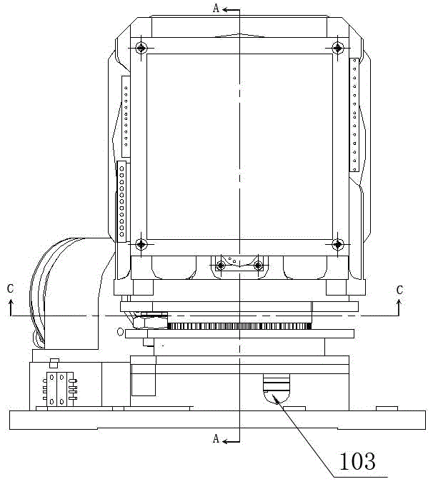
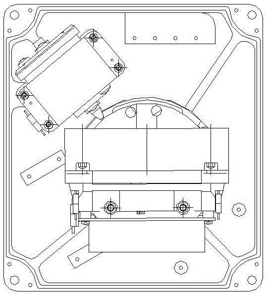
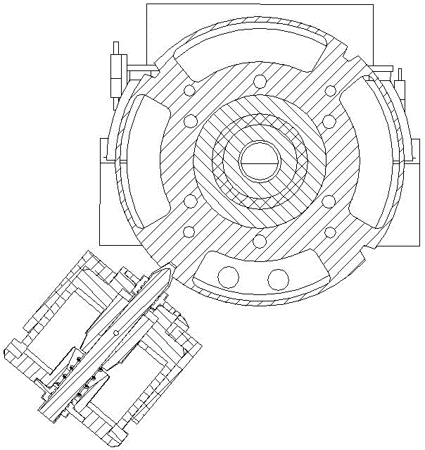
[0037] Figure 1-12It is a structural diagram of a fiber optic gyro north finder, including a base 9, a transmission device 16, a rotating shaft 22, an indexing plate 7, a bracket 1 and a cable I20, the transmission device 16 is fixedly arranged on the base 9, and the rotating shaft 22 is vertical Set on the transmission device 16, the index plate 7 is fixedly arranged on the rotating shaft 22, the disk surface 26 of the index plate 7 is perpendicular to the axis 28 of the rotating shaft, the support 1 is provided with a support chassis 5 and a support body 2, the support chassis 5 and The support body 2 is connected as a whole, the support body 2 is perpendicular to the support chassis 5, and the support chassis 5 is fixed on the indexing plate 7; the support body 2 is fixedly provided with a detection system 101 and a circuit board 3, and the detection system 101 includes a Accelerometer 4 and a fiber optic gyroscope 23, the detection system 101 is used to detect the acceler...


PUM


Abstract

The invention discloses a fiber optic gyro north finder. The fiber optic gyro north finder comprises a base, a transmission device, a rotating shaft, an indexing disk, a bracket, a cable I, a hollow cup motor, a motor outer seat, a motor base, a bearing part, a bearing outer pressure ring, a bearing inner pressure ring and a carbon film part, wherein the bracket is provided with a bracket chassis and a bracket body; the bracket chassis and the bracket body are connected integrally; the bracket body is perpendicular to the bracket chassis; the bracket chassis is fixed to the indexing disk; the bracket body is fixedly provided with a detection system and a circuit board; the detection system comprises an accelerator and a fiber optic gyro; the detection system is used for detecting gravity acceleration and a rotation horizontal component of an earth; the cable I penetrates out of the base after passing through a groove of the bracket chassis, a gap of the rotating shaft, a through hole of the rotating shaft and a cable hole of the base in sequence. According to the fiber optic gyro north finder, an anti-cable winding structure is not adopted, so that the structure is simplified; the hollow cup motor is adopted, so that components are reduced, the system size is reduced, and the fiber optic gyro north finder has the advantages of simple structure, compactness and high north finding accuracy.

Description

technical field [0001] The present invention relates to the technical field of inertial navigation, in particular to a fiber optic gyro north finder. Background technique [0002] The fiber optic gyro north finder is a high-precision inertial instrument that can automatically indicate the orientation in all weathers under static conditions. It uses the earth's rotation angular rate component measured by the fiber optic gyro and the gyro axial horizontal error angle measured by the accelerometer to obtain the angle between the reference axis fixed on it and the true north direction through calculation, so as to obtain a certain value of the carrier. An angle between a fixed axis and the north direction. [0003] In the fiber optic gyro north finder, there are generally two-position method, four-position method and multi-position method to work. Among them, the north finder using the principle of the four-position method is more commonly used, but it has the following defects...

Claims


Application Information

Patent Timeline
Patent Type & Authority Patents(China)
IPC IPC(8): G01C19/72
CPCG01C17/00G01C19/64G01D5/1655H02G11/00
Inventor 谢箭王福亮任莎莉吕丰宝李红良
Owner CHONGQING HUAYU ELECTRIC GRP
Learn More