Vector measurement method for passive intermodulation interference
A measurement method, passive intermodulation technology, applied in the field of vector measurement of passive intermodulation interference, can solve the problems of phase difference, no intermodulation calibration or suppression of the instrument itself, no vector measurement method, etc., to reduce self-interference The effect of adjusting and reducing the measurement uncertainty
- Summary
- Abstract
- Description
- Claims
- Application Information
AI Technical Summary
Problems solved by technology
Method used
Image
Examples
Embodiment 1
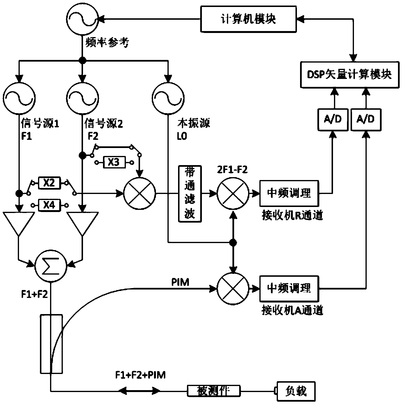
[0048] The passive intermodulation (PIM) vector measuring instrument of the present invention can perform vector measurement on reflected PIM products, and its phase is relative to the PIM reference information generated by the mixing of two-tone signals. Its working principle is as follows figure 1 shown.
[0049]Firstly, the computer module adjusts the output frequency of the frequency reference unit, and outputs a frequency reference signal. After power division, they are respectively used by signal source 1, signal source 2 and local oscillator source modules to generate test signals of frequencies F1 and F2 and local oscillator signals of L0. After power division of the test signals F1 and F2, part of it is amplified by the amplifier module, combined to generate a +43dBm dual-tone signal for testing, and part of it is mixed with each other through the frequency multiplier module, and after filtering, it is frequency 2F1-F2, which is received by the reference receiver as P...
Embodiment 2
[0068] On the basis of the above embodiments, the present invention is further described, a vector measurement method of passive intermodulation interference, which includes the following steps:
[0069] Step 1: The computer module adjusts the output frequency reference signal of the frequency reference unit, and after power division, it is respectively used by the first signal source, the second signal source and the local oscillator source module to generate the test signals of frequencies F1 and F2 and the local oscillator signal of L0 ;
[0070] Step 2: The first signal source is divided or coupled into two signals, the first signal and the second signal respectively, the first signal enters the frequency multiplication unit, and the second signal enters the power amplifier; the second signal source is divided or coupled The two channels are the third signal and the fourth signal, the third signal enters the frequency multiplier unit, and the fourth signal enters the power...
PUM
 Abstract
Description
Claims
Application Information
 - R&D
- Intellectual Property
- Life Sciences
- Materials
- Tech Scout
- Unparalleled Data Quality
- Higher Quality Content
- 60% Fewer Hallucinations
Browse by: Latest US Patents, China's latest patents, Technical Efficacy Thesaurus, Application Domain, Technology Topic, Popular Technical Reports.
© 2025 PatSnap. All rights reserved.Legal|Privacy policy|Modern Slavery Act Transparency Statement|Sitemap|About US| Contact US: help@patsnap.com


