
Printed circuit element polarity machine vision detection method and device

A machine vision inspection, printed circuit technology, applied in the direction of instruments, measuring electricity, measuring devices, etc., can solve problems such as lack of interference, achieve the effect of improving product quality, improving the degree of inspection automation, and saving personnel costs

Inactive Publication Date: 2014-03-26
CHINA UNIV OF MINING & TECH
View PDF6 Cites 31 Cited by
  • Summary
  • Abstract
  • Description
  • Claims
  • Application Information

AI Technical Summary

Problems solved by technology

Both of the above methods lack the ability to remove the interference caused by light intensity

Method used


Image

  • Printed circuit element polarity machine vision detection method and device
  • Printed circuit element polarity machine vision detection method and device
  • Printed circuit element polarity machine vision detection method and device

Examples


Embodiment Construction

[0042] An embodiment of the present invention will be further described below in conjunction with accompanying drawing:

[0043] The machine vision detection method of the printed circuit element polarity of the present invention comprises the following steps:

[0044] (1) Place different types of components to be tested in sequence in the test area of ​​a closed work box containing an adjustable light source, take multiple photos for each type of component, and obtain component samples;

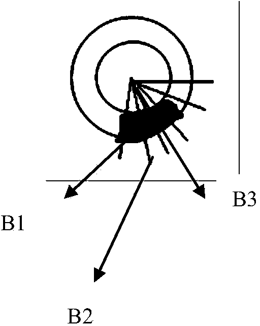
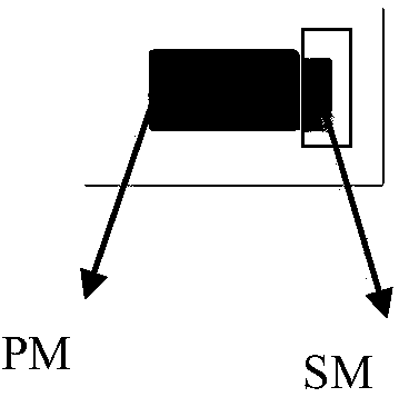
[0045] (2) For component samples, classify according to the type of capacitance or diode, determine the detection parameters required for each type of component to be tested, and form all the used detection parameters into a detection parameter set; the detection parameter set is: to be detected Component model, capacitor polarity identification binarization threshold, capacitor polarity identification direction, capacitor body outline circle diameter and pixel area size, capacitor polarity ...


PUM


Abstract

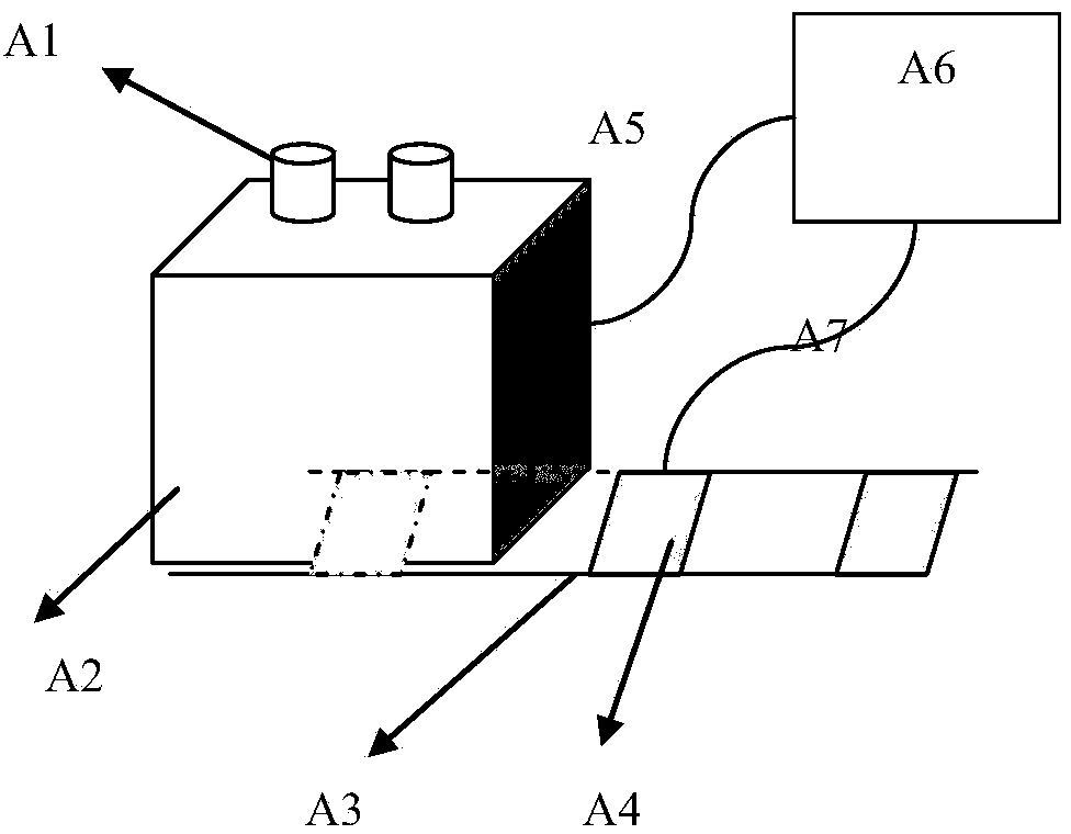
Provided is a printed circuit element polarity machine vision detection method and a device. A guide rail used for conveying a printed circuit board to be detected is arranged in a test area. The guide rail is provided with stroke switches controlled by sensors. An enclosed working case covering the test area is arranged above the guide rail. The internal part of the enclosed working case is provided with a light source capable of adjusting brightness, and multiple sensors. Different types of elements to be detected are arranged in the test area of the enclosed working case with the light source capable of adjusting brightness in turn, and element samples are acquired. Categorization is performed according to model numbers of capacitors or diodes, and detection parameters required by the elements to be detected are confirmed. Aiming at difference of positions of the printed circuit board elements, the corresponding positions of different elements on the circuit board are designated, and corresponding standard model types of different printed circuit boards are formulated via model type identification symbols, the element model numbers, the positions and detection parameter values. A machine vision mode is utilized to substitute a manual vision detection mode so that situations of staff negligence and errors of leak detection of polarity directions of the polarity elements are reduced, production cost is reduced and production quality is enhanced.

Description

technical field [0001] The invention relates to a method and equipment for a circuit board with polarity marking electrolytic capacitors and diodes, in particular to a polarity of printed circuit components suitable for detecting whether the polarity of electrolytic capacitors and diodes mounted on the circuit board is correct Machine vision inspection methods and equipment. Background technique [0002] Printed PCB board is an important part of the modern electronics industry, and its quality directly affects the performance of the product. Component soldering on printed circuit boards is the basic workflow for custom circuit boards. On the assembly line, due to the high-density and rapid assembly of PCB board components, it brings great difficulties to traditional manual online detection and analysis. Among them, the electronic components packaged with double rows of pins are still mostly assembled by hand to be inserted into the printed circuit board. The direction of ...

Claims


Application Information

Patent Timeline
IPC IPC(8): G01R31/02
Inventor 鲍宇陈映周娟赵亮孟鑫
Owner CHINA UNIV OF MINING & TECH
Learn More