Seismic diffracted wave separating and imaging method

An imaging method and diffraction wave technology, applied in seismic signal processing and other directions, can solve problems such as low precision, unclean reflection wave suppression, and difficulty in identifying weak diffraction energy

Active Publication Date: 2014-03-26
CHINA PETROLEUM & CHEM CORP +1
View PDF5 Cites 32 Cited by
  • Summary
  • Abstract
  • Description
  • Claims
  • Application Information

AI Technical Summary

Problems solved by technology

[0006] However, the limitation of this method is that it is suitable for use when the structure of the underground medium is relatively simple and the signal-to-noise ratio is relatively high, and there are still a large number of residual reflection waves in the diffraction wave data separated by this method, and the diffraction wave loss In addition, this method can only be used for stacked seismic data, and cannot obtain diffraction wave records in the original shot domain, which is not conducive to later processing
Affected by the reflected wave from the strong wave-resistance interface, it is difficult to identify the weakly diffracted energy of small fracture-cavity bodies in the imaging results. The current F-K domain (time-frequency domain) filtering method for separating diffracted waves has low accuracy and the reflection The wave suppression is not clean, and the scope of application is small

Method used


Image

  • Seismic diffracted wave separating and imaging method
  • Seismic diffracted wave separating and imaging method
  • Seismic diffracted wave separating and imaging method

Examples


Embodiment Construction

[0068] Below in conjunction with accompanying drawing, the present invention is described in further detail:

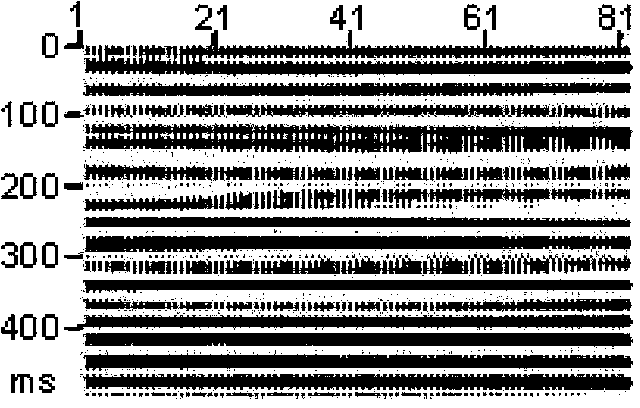
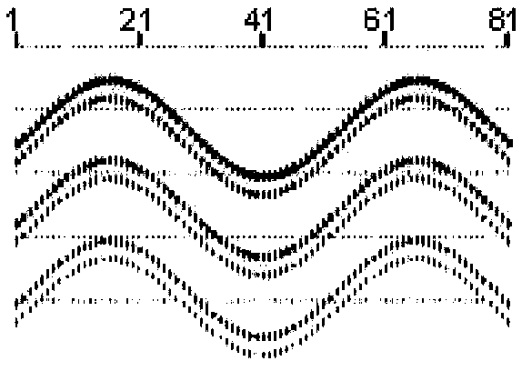
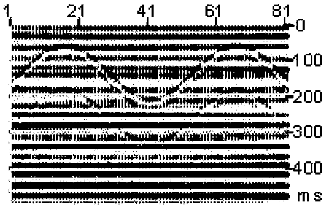
[0069] The present invention addresses the problem of diffraction wave separation in seismic recording. According to the difference in inclination angle and linear predictability between diffracted waves and reflected waves in the plane wave domain, after plane wave decomposition of the original seismic records, data rearrangement is carried out to obtain plane wave records with different slope parameters. In order to obtain the high-inclination diffracted wave records in the plane wave domain through plane wave filtering, and then separate the low-inclination diffracted wave records in the plane wave domain through prediction and inversion for the remaining data after removing the high-inclination diffracted waves, Add the separated high-inclination diffraction wave records and low-inclination diffraction wave records to obtain a relatively complete diffraction wave ...


PUM


Abstract

The invention provides a seismic diffracted wave separating and imaging method and belongs to the field of imaging processing and fracture-cave reservoir prediction in geophysical exploration of petroleum. According to the method, diffracted waves are separated from an original seismic record according to the difference between reflected waves and diffracted waves, and the separated diffracted waves are imaged independently. Diffracted wave information obtained through the method provided by the invention is complete, the diffracted wave imaging result has relatively high lateral resolution, and meanwhile, the result of independent imaging of the diffracted waves eliminates an interference effect on the diffracted waves caused by reflected waves, directly reflects the location information of a fracture-cave reservoir body and is conducive to improving the accuracy of identification of the fracture-cave reservoir body.

Description

technical field [0001] The invention belongs to the fields of imaging processing and fracture-cavity reservoir prediction in petroleum geophysical prospecting, and in particular relates to a seismic diffraction wave separation imaging method. Background technique [0002] Diffraction waves are markers of structural and lithological anomalies and can be generated wherever discontinuities exist, such as caves, fractures, faults, pinch-outs, reefs, salt domes, weathering crust, intrusive rocks, and oil-moisture The edge of the interface is where the diffracted wave develops. The reflected wave is a comprehensive reflection of the geological background, and the diffracted wave is the reflection of geological details, which is an important information carrier for improving seismic resolution. In the raw data of seismic exploration, there are both diffracted waves and reflected waves. During the imaging process of the data, the diffracted waves and reflected waves are also unifor...

Claims


Application Information

Patent Timeline
Patent Type & Authority Applications(China)
IPC IPC(8): G01V1/28G01V1/32G01V1/36
Inventor 朱生旺李佩宁俊瑞
Owner CHINA PETROLEUM & CHEM CORP
Why Eureka
Try Eureka