
Method for identifying and effectively suppressing signal resonance interference during microseismic monitoring

A technology for resonance interference and monitoring signals, which is applied in seismic signal processing and other directions, can solve the problems of microseismic event positioning result errors, damage signal integrity, and affect microseismic monitoring data processing effects, etc., to achieve high computing efficiency and simple use Effect

Active Publication Date: 2014-03-26
BC P INC CHINA NAT PETROLEUM CORP +1
View PDF6 Cites 6 Cited by
  • Summary
  • Abstract
  • Description
  • Claims
  • Application Information

AI Technical Summary

Problems solved by technology

In this way, resonance interference can be suppressed to a certain extent, but the frequency spectrum of the signal itself is changed, and the effective signal in this frequency band is also suppressed, which destroys the integrity of the signal to a certain extent; especially affects the take-off point of the arrival time of the microseismic event, which is very important for accurately picking up the microseismic event. The arrival time of the event is affected, which affects the processing effect of the microseismic monitoring data and causes a large error in the positioning result of the microseismic event

Method used


Image

  • Method for identifying and effectively suppressing signal resonance interference during microseismic monitoring
  • Method for identifying and effectively suppressing signal resonance interference during microseismic monitoring
  • Method for identifying and effectively suppressing signal resonance interference during microseismic monitoring

Examples


Embodiment Construction

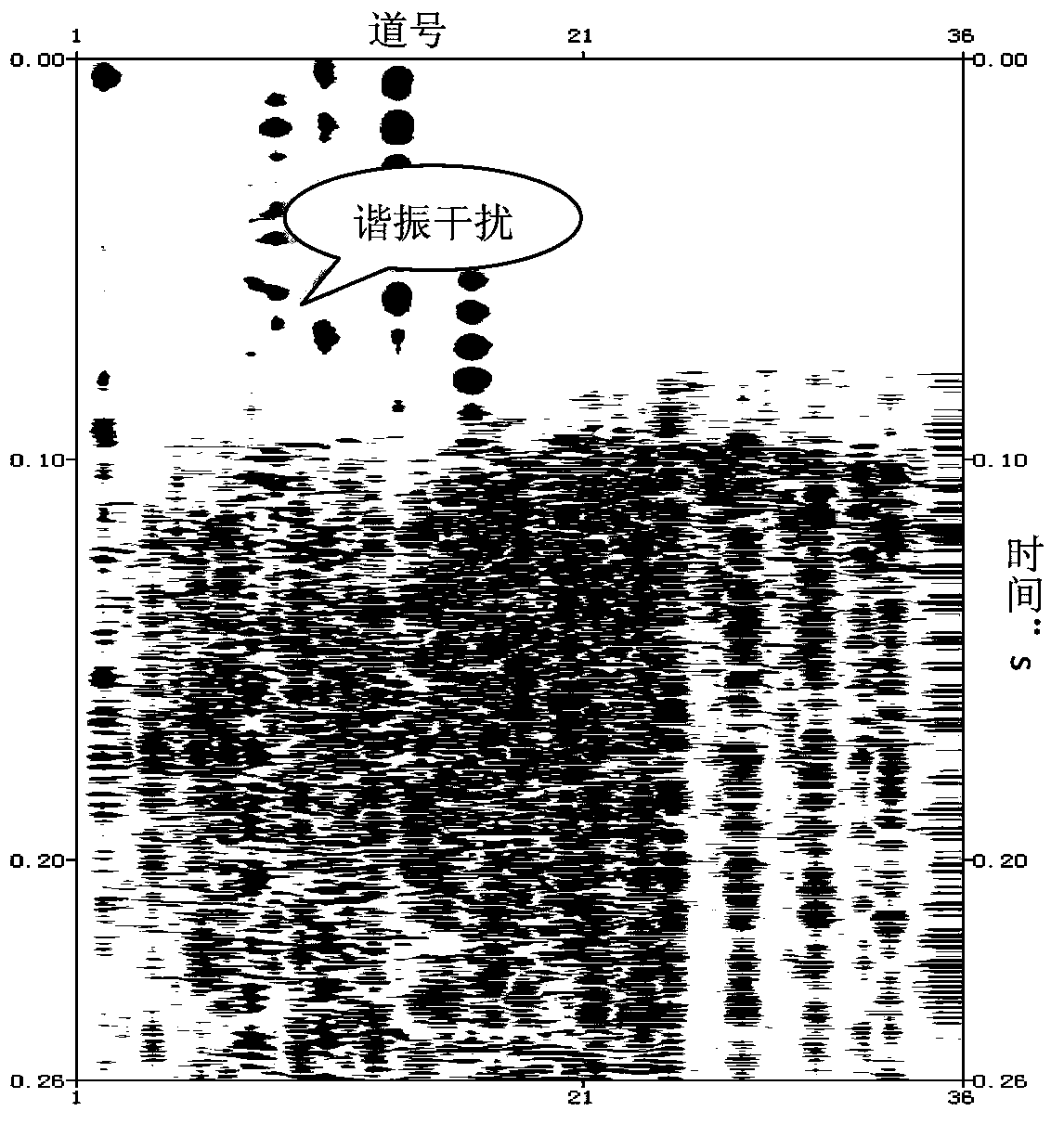
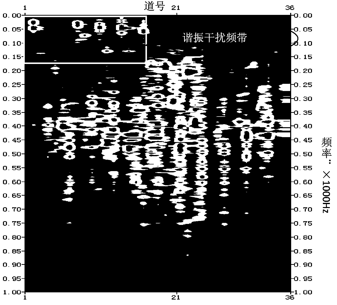
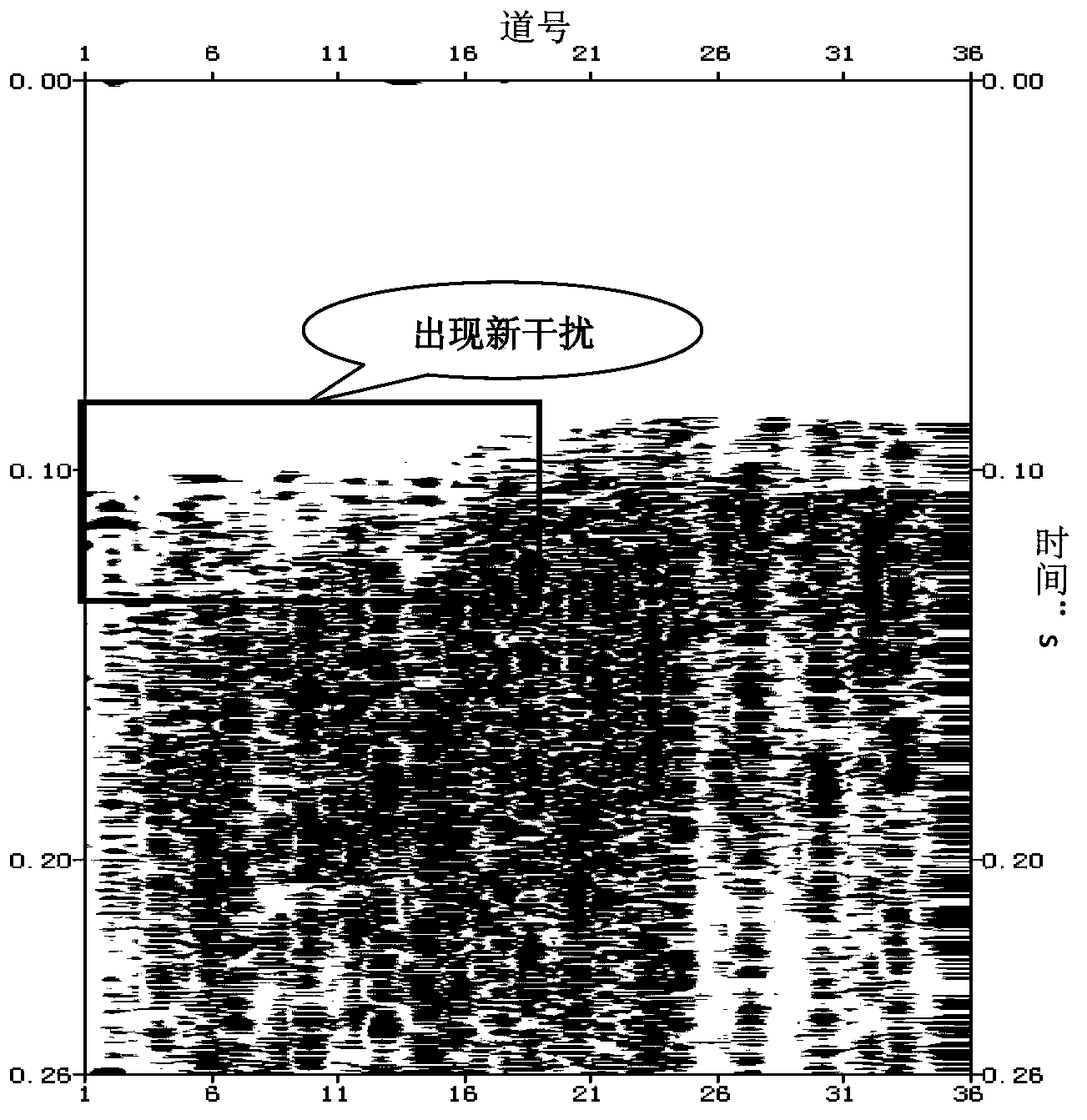
[0026] In the invention, in the processing of fracturing microseismic monitoring data, the resonance signal in the microseismic monitoring signal is suppressed by using the spectrum compensation method. The first is to convert the signal to the frequency domain, identify the resonant frequency band of each detector, and make reasonable compensation to the resonant frequency band in the frequency domain, so as to reach an effective signal that minimizes damage and suppress resonance interference very effectively.

[0027] Below in conjunction with accompanying drawing, describe the present invention in detail, the specific implementation steps of the present invention are as follows:

[0028] 1) Use the downhole three-component geophone to collect the microseismic event signals generated during oil field fracturing construction in the well;

[0029] 2) Identify microseismic signals based on the energy ratio of microseismic event signals, figure 1 There is obvious resonance int...


PUM


Abstract

The invention provides a method for identifying and suppressing signal resonance interference during microseismic fracture monitoring. The method comprises the following steps: transferring microseismic fracture event signals into a frequency domain; respectively arranging three-component spectrum in terms of horizontal and vertical component; determining the resonance signal band frequency range; selecting a non-resonance interference spectrum channel on the vertical component spectrum arrangement; calculating the energy of a frequency sampling point and that of whole-channel signal master frequency, wherein the ratio of the two energies is a relative attenuation coefficient of the microseismic signal at the sampling point; calculating the master frequency energies of all resonance interference spectrum of each arrangement of the three-component spectrum, allowing the result to multiply the attenuation coefficient of the corresponding sampling point to obtain a spectrum compensation value for resonance interference band frequency compensation; transforming the frequency domain signals to a time domain through an inverted Fourier transform so as to complete suppressing of resonance signals. Due to the adoption of the method, the resonance interference in microseismic signals can be effectively identified and suppressed, so as to minimize the damage for effective signals. Therefore, the method is simple to use and high in calculation efficiency.

Description

technical field [0001] The invention relates to a fracturing microseismic monitoring data processing technology, in particular to a method for identifying resonance interference of a microseismic monitoring signal and effectively suppressing it. Background technique [0002] Fracturing microseismic monitoring refers to the monitoring of microseismic events caused by rock fractures during oilfield fracturing construction. Due to the special downhole acquisition method and the poor coupling between the downhole geophone and the borehole wall, the fracturing microseismic monitoring signals often have resonance interference in the acquired data, which has a great impact on the data processing. [0003] Due to the long duration of fracturing microseismic monitoring signals and the huge amount of data, it is impossible to process a small part of the signals separately. At present, the batch band-pass filtering method is mainly used for resonance interference in fracturing microsei...

Claims


Application Information

Patent Timeline
Patent Type & Authority Applications(China)
IPC IPC(8): G01V1/36
Inventor 容娇君李彦鹏徐刚储仿东李飞刘博张彦斌张固澜衡峰刘腾蛟
Owner BC P INC CHINA NAT PETROLEUM CORP
Learn More