Coupled antenna and complete machine testing system

A coupling antenna and whole machine testing technology, applied in the field of coupling testing, can solve the problems of high false detection rate and low coupling efficiency, and achieve the effect of improving the coupling rate

Active Publication Date: 2014-03-26
HONOR DEVICE CO LTD
View PDF6 Cites 12 Cited by
  • Summary
  • Abstract
  • Description
  • Claims
  • Application Information

AI Technical Summary

Problems solved by technology

[0006] The purpose of the present invention is to provide a coupling antenna and a complete machine test system to solve the problem of using the transmission line contained in the traditional coupling boar

Method used


Image

  • Coupled antenna and complete machine testing system
  • Coupled antenna and complete machine testing system
  • Coupled antenna and complete machine testing system

Examples


Example Embodiment

[0042] In order to make the object, technical solution and advantages of the present invention clearer, the present invention will be further described in detail below in conjunction with the accompanying drawings and embodiments. It should be understood that the specific embodiments described here are only used to explain the present invention, not to limit the present invention.

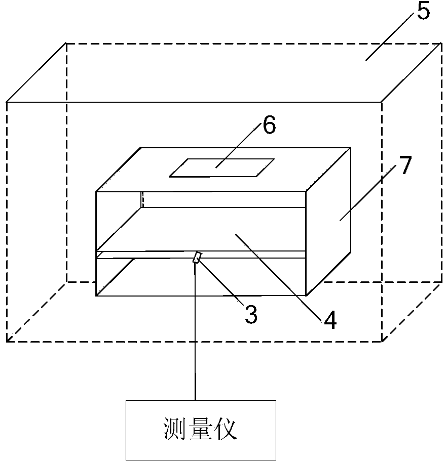
[0043] In order to illustrate the technical scheme described in the present invention, below with figure 2As an example, the detailed description of the present invention is the structure of the coupling antenna provided by the invention; but it should be noted that the coupling antenna provided by the embodiment of the present invention cannot be figure 2 As a limit, may not be made on a printed circuit board.

[0044] A coupled antenna comprising:

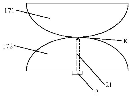
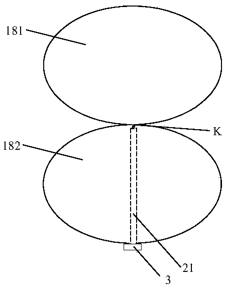
[0045] A symmetrical vibrator, used for coupling radio frequency signals of a preset frequency band; the symmetrical vibrator includes two symmet...


PUM


Abstract

The invention belongs to the field of coupling testing and provides a coupled antenna and a complete machine testing system. The coupled antenna comprises a dipole used for coupling radio-frequency signals of a preset frequency band, a feeder line and a coupling testing interface. The dipole comprises two symmetric antenna elements and one of the symmetric antenna elements is grounded; one end of the feeder line is connected to a connecting point on the symmetric axis of the dipole and used for transmitting the radio-frequency signals received by coupling of the dipole to the coupling test interface; the coupling test interface is arranged at the other end of the feeder line and used for being externally connected with a gauge so as to accomplish whole machine testing. Thus, in the complete machine testing system, the coupled antenna is used for replacing a traditional coupling board and the coupling efficiency of the radio-frequency signals sent by the antenna of a coupling terminal device is improved, so that complete machine testing is accurately conducted through the radio-frequency signals coupled by the coupled antenna.

Description

technical field [0001] The invention belongs to the field of coupling testing, in particular to a coupling antenna and a complete machine testing system. Background technique [0002] For terminal equipment (including mobile phones, data cards, network cards, notebooks and other terminals using wireless communication technology), after the production and assembly are completed, it must be tested for the whole machine (Mobile Test, MT) to test the wireless performance. [0003] At present, the whole machine test system using the traditional coupling board, such as figure 1 As shown, the terminal device 6 is placed on the upper part of the plastic fixture 7 during the whole machine test, and the coupling plate 4 is located in the middle of the same plastic fixture 7, and a certain distance is formed between the terminal device 6 and the coupling plate 4; in order to prevent external interference, The plastic fixture 7 is placed in the shielding box 5; in addition, the couplin...

Claims


Application Information

Patent Timeline
IPC IPC(8): H01Q1/36H01Q1/38H01Q1/50
Inventor 刘钊许安民郝卫东
Owner HONOR DEVICE CO LTD
Why Eureka
Try Eureka