
A three-bridge-arm topology circuit, its control method, and an uninterruptible power supply system

A technology of topology circuit and three bridge arms, applied in circuit devices, emergency power supply arrangements, battery circuit devices, etc., can solve the problems of increased system cost, low integration and device utilization, etc., to achieve high power density and reduce current stress. Risk and heat loss risk, effect of reducing heat risk

Active Publication Date: 2015-11-25
HUAWEI DIGITAL POWER TECH CO LTD
View PDF5 Cites 0 Cited by
  • Summary
  • Abstract
  • Description
  • Claims
  • Application Information

AI Technical Summary

Problems solved by technology

As a result, the integration level of the existing UPS system and the utilization rate of the components are not high, which increases the cost of the system

Method used


Image

  • A three-bridge-arm topology circuit, its control method, and an uninterruptible power supply system
  • A three-bridge-arm topology circuit, its control method, and an uninterruptible power supply system
  • A three-bridge-arm topology circuit, its control method, and an uninterruptible power supply system

Examples


Embodiment 2

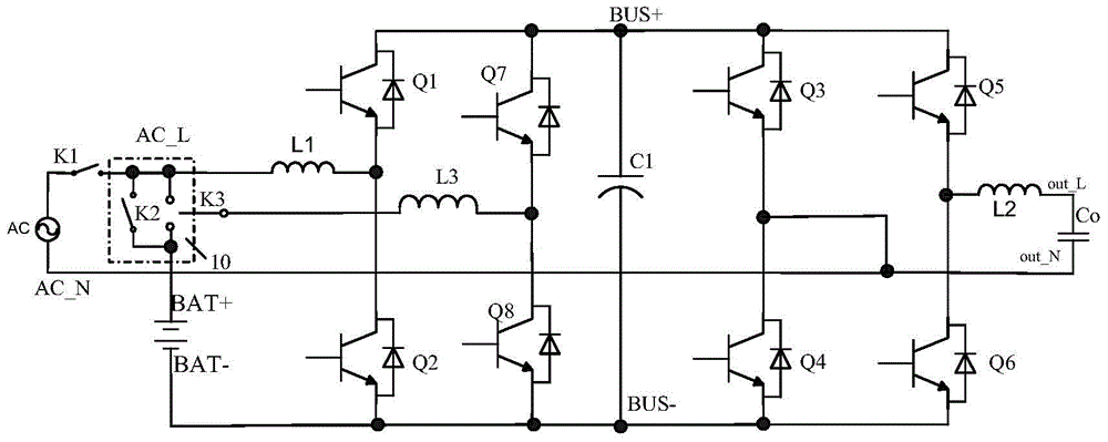
[0099] In the second embodiment, the first switching transistor Q1 to the sixth switching transistor Q6 form a traditional three-leg topology, and the structure is the same as that of the first embodiment, and will not be repeated here.

[0100] In the second embodiment, the circuit further includes: a bidirectional switching bridge arm. Wherein, the bidirectional switching bridge arm includes: a seventh switching tube Q7 , an eighth switching tube Q8 , a third inductor L3 and a switching switch 10 .

[0101] Such as Figure 11 As shown, the seventh switch tube Q7 and the eighth switch tube Q8 are connected in series between the positive output terminal of the BUS and the negative output terminal of the BUS.

[0102] The common end of the seventh switching tube Q7 and the eighth switching tube Q8 is connected to the first end of the third inductance L3, and the second end of the third inductance L3 is connected to the first end of the switch 10 .

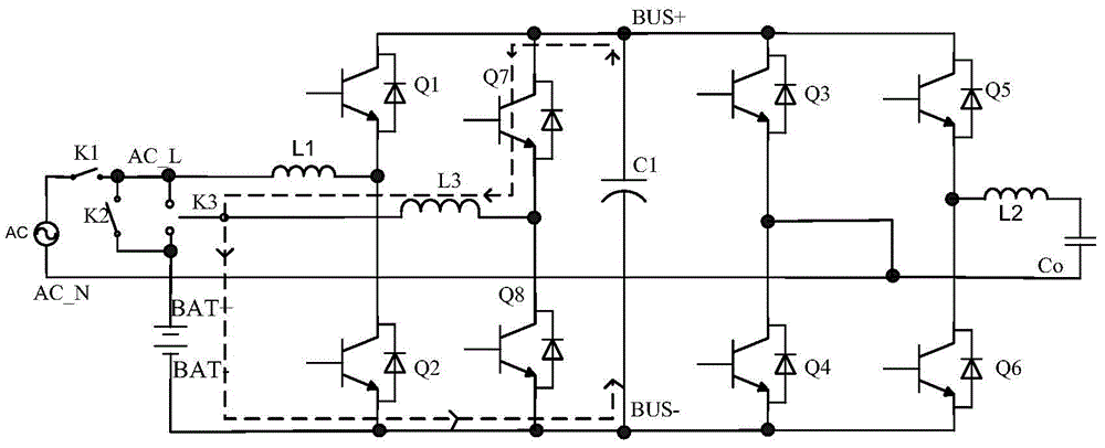
[0103] Such as Figure 1...


PUM


Abstract

The embodiment of the invention discloses a three-bridge-arm topology circuit. The circuit comprises three bridge arms and a bi-directional conversion bridge arm, wherein the three bridge arms are connected between the positive output end and the negative output end of a BUS in parallel. The middle point of the bi-directional conversion bridge arm is connected with the first end of a selector switch through a third inductor. The third end of the selector switch is connected with the positive voltage input end of the circuit. A battery pack of the circuit is connected between the second end of the selector switch and one output end of the BUS. The selector switch is used for controlling the bi-directional conversion bridge arm to charge the battery pack when the battery pack is in a mains supply mode and low in voltage. In the mains supply mode, when the battery pack is fully charged or a mains supply is low in voltage, the bi-directional conversion bridge arm is controlled to discharge the battery pack. The embodiment of the invention further discloses an uninterrupted power supply system and a control method of the three-bridge-arm topology circuit. By the adoption of the circuit, the control method and the uninterrupted power supply system, the integration level of the system and the utilization rate of components can be improved, system cost can be reduced, besides, the heat risk of the system can be reduced, and reliability of the system is improved.

Description

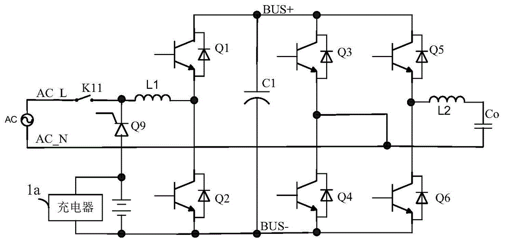
technical field [0001] The invention relates to the technical field of uninterruptible power supply, in particular to a three-bridge arm topology circuit, a control method, and an uninterruptible power supply system. Background technique [0002] Compared with the traditional bilateral bus topology, the online small and medium power UPS (Uninterrupted Power Supply, uninterrupted power supply) system of the three-bridge arm topology has the advantages of halving the bus capacitance and reducing the number of power tubes, and has become a low-cost online UPS. The focus of technology research. [0003] refer to figure 1 , the circuit diagram for the uninterruptible power supply system of the traditional three-leg topology. Such as figure 1 As shown, the traditional three-leg topology can include: the PFC (PowerFactorCorrection, power factor correction) side high-frequency bridge arm composed of switch tubes Q1 and Q2; the power frequency bridge arm shared by PFC and INV comp...

Claims


Application Information

Patent Timeline
Patent Type & Authority Patents(China)
IPC IPC(8): H02J9/06H02J7/00
Inventor 杨婷程洋王富洲
Owner HUAWEI DIGITAL POWER TECH CO LTD
Learn More