
Third-harmonic excitation synchronous motor

A synchronous motor and sub-harmonic technology, applied in the field of new third-harmonic excitation synchronous motor, can solve the problems of increasing the maintenance workload and manufacturing cost of the motor, reducing the reliability of motor operation, etc., achieving convenient control, reducing manufacturing costs, and easy The effect of adjustment

Active Publication Date: 2014-03-26
NANCHANG UNIV
View PDF3 Cites 15 Cited by
  • Summary
  • Abstract
  • Description
  • Claims
  • Application Information

AI Technical Summary

Problems solved by technology

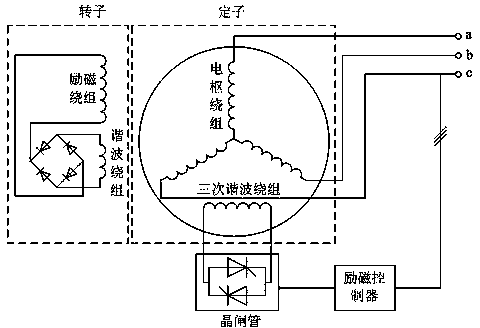
[0004] Compared with the fundamental phase compound excitation, the excitation method using the third harmonic excitation has the advantages of simple circuit, fast response and good phase compound excitation characteristics. However, since the third harmonic winding is on the stator side, it needs the use of brushes and The electric ring is input into the rotor excitation winding to form a brushed third harmonic excitation synchronous generator, or to form a brushless third harmonic excitation synchronous generator with the help of an AC exciter, thereby reducing the reliability of the motor operation and increasing the Efforts for motor maintenance and manufacturing costs

Method used


Image

  • Third-harmonic excitation synchronous motor
  • Third-harmonic excitation synchronous motor
  • Third-harmonic excitation synchronous motor

Examples


Embodiment Construction

[0022] The present invention will be described in further detail below in conjunction with the accompanying drawings and specific embodiments.

[0023] Example.

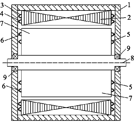
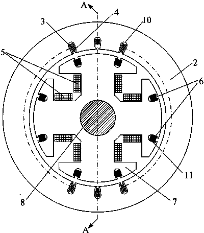
[0024] Depend on figure 1 and figure 2 It can be seen that the novel third-harmonic excitation synchronous motor of the present invention includes a casing in which a stator core is arranged, and slots are slotted along the circumferential direction on the stator core, and stator armature windings and stator third-harmonic windings are arranged in the slots. The casing and the stator core are fixed, and a rotating shaft is arranged in the casing, and the rotating shaft is connected with the casing through a bearing. The rotor excitation winding is arranged on the rotor pole body, and the rotor harmonic winding is distributed in the slots on the rotor core along the circumferential direction. The rotor excitation winding, the rotor harmonic winding and the rotor core can rotate together with the rotating shaft in ...


PUM


Abstract

The invention discloses a third-harmonic excitation synchronous motor. The third-harmonic excitation synchronous motor comprises a motor case, a stator core, a stator armature winding, a stator third-harmonic winding, a rotor core, a rotor excitation winding, a rotor harmonic winding and a rotary shaft, wherein the armature winding and the third-harmonic winding are arranged in a stator groove, a magnetic pole body is sleeved with the excitation winding, the harmonic winding is arranged in a rotor groove, the short circuit of the third-harmonic winding is achieved through an anti-parallel thyristor, the phase position of trigger pulses of the thyristor is given by an excitation controller, and the excitation winding and the harmonic winding are connected through a diode rectification circuit. According to the third-harmonic excitation synchronous motor, electromotive force induced by the third-harmonic winding is transmitted to the excitation winding for excitation through the magnetic coupling between the stator third-harmonic winding and the rotor harmonic winding, an electric brush and a collecting ring or an alternating-current exciter are omitted, and the third-harmonic excitation synchronous motor has the advantages of being high in reliability, small in maintenance amount, low in manufacturing cost and the like; adjustment of the voltage of a motor end is achieved by controlling the phase position of the trigger pulses of the anti-parallel thyristor, and the third-harmonic excitation synchronous motor further has the advantages of being convenient to control and easy to adjust.

Description

technical field [0001] The invention relates to an electric excitation synchronous motor, in particular to a novel third harmonic excitation synchronous motor. Background technique [0002] Harmonic magnetic fields in motors exist objectively, and efforts are usually made to weaken or eliminate the influence of harmonics on motor performance. However, under the premise of not affecting the performance of the motor, using harmonics for excitation is a clever use of the harmonic magnetic field in the motor. Since the 1970s, some domestic scholars and technicians in electrical machinery factories began to study the use of the third harmonic magnetic field in the air gap, and successfully applied it to the excitation system of synchronous generators, forming a third harmonic excitation synchronous generator. [0003] The structure of the three-harmonic excitation synchronous motor is similar to that of the ordinary synchronous motor. The difference is that in addition to the a...

Claims


Application Information

Patent Timeline
IPC IPC(8): H02K19/12H02K19/28
Inventor 夏永洪黄新黄劭刚龚文军陈瑛杨玉文张景明
Owner NANCHANG UNIV
Learn More