Clock synchronization device and method

A clock synchronization and local clock technology, applied in the wireless field, can solve the problems of decreased channel measurement accuracy, low measurement efficiency, inability to eliminate the frequency difference and phase difference of the local oscillator at the transceiver end, and achieve the effect of improving the clock synchronization accuracy

Inactive Publication Date: 2014-03-26
CHINA MOBILE COMM GRP CO LTD
View PDF3 Cites 9 Cited by
  • Summary
  • Abstract
  • Description
  • Claims
  • Application Information

AI Technical Summary

Problems solved by technology

This method is generally used for short-distance fixed scene measurement, but for long-distance multi-scenario high-speed rail channel measurement, the measurement efficiency of this method is extremely low
The clock synchronization method of efficient channel measuring instrument can eliminate the frequency deviation and phase deviation of the local oscillator at the transceiver end by using related signal processing methods, but in the case of Doppler frequency offset, it will greatly affect the performance of the correlation algorithm, and cannot eliminate the local oscillator at the transceiver end The frequency difference and phase difference will lead to errors in the extraction of Doppler frequency offset parameters, resulting in a decrease in channel measurement accuracy
Therefore, the existing clock synchronization methods cannot meet the efficiency and accuracy of high-speed rail channel measurement

Method used


Image

  • Clock synchronization device and method
  • Clock synchronization device and method
  • Clock synchronization device and method

Examples


Embodiment Construction

[0045] The present invention will be further described in detail below in conjunction with the accompanying drawings and specific embodiments.

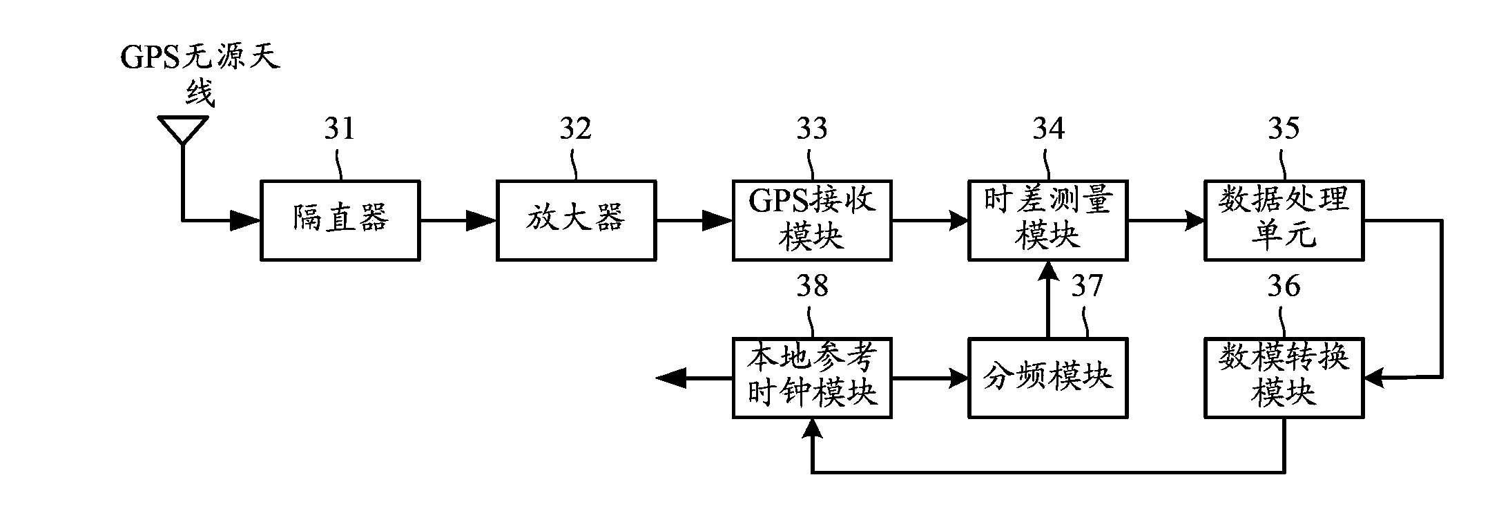
[0046] image 3 A schematic diagram of the composition of the clock synchronization device provided by the embodiment of the present invention, such as image 3 As shown, it mainly includes: a DC blocker 31, an amplifier 32, a GPS receiving module 33, a local clock reference module 34, a frequency division module 35, a time difference measurement module 36, a data processing module 37 and an analog-to-digital conversion module 38, wherein:

[0047]DC blocker 31: for receiving GPS signals from the passive antenna of the Global Positioning System (GPS, Global Positioning System), outputting the GPS signals to the amplifier 32, and blocking the current when receiving the current fed back by the amplifier 32.

[0048] When this embodiment is applied to high-speed rail channel measurement, the channel measuring instrument is located on th...


PUM


Abstract

The invention discloses a clock synchronization device and method. The clock synchronization device comprises a DC (Direct Current) block, an amplifier, a GPS (Global Positioning System) receiving module, a local clock reference module, a frequency dividing module, a time difference measuring module, a data processing module and an analog-digital converting module, wherein the DC block is used for outputting GPS signals from a parasitic antenna to the amplifier and cutting off a current fed back by the amplifier; the amplifier is used for amplifying the GPS signals and outputting the GPS signals to the GPS receiving module; GPS second pulse signals are obtained according to the GPS signals, and outputted to the time difference measuring module; the local clock reference module is used for outputting local clock reference signals to the frequency dividing module and correcting the local clock reference signals according to an analog voltage sent by the analog-digital converting module; the frequency dividing module is used for dividing the local clock reference signals into the second pulse signals and outputting the second pulse signals to the time difference measuring module; the time difference measuring module is used for measuring the time difference between the local clock second pulse signals and the GPS second pulse signals, and sending the time difference to the data processing module; a frequency deviation is obtained according to the time difference and sent to the analog-digital converting module; the analog-digital converting module is used for converting the frequency deviation into an analog voltage and sending the analog voltage to the local clock reference module. According to the invention, the clock synchronization precision is improved.

Description

technical field [0001] The invention relates to the field of wireless technology, in particular to a clock synchronization device and method. Background technique [0002] High-speed railway is the trend of railway development in the world today. The communication between the high-speed train and the ground has become a hot issue in the research of broadband wireless communication at home and abroad. With the development of high-speed railways, railway informatization requires more and more communication data between trains and ground. On the one hand, real-time information such as train operation, train safety monitoring, and maintenance needs to be transmitted to the ground to meet the needs of the railway network for real-time dynamic tracking and information transmission of moving objects (locomotives, vehicles, etc.); on the other hand, passengers are the main body The mobile information needs to be transmitted between the vehicle and the ground in real time. However...

Claims


Application Information

Patent Timeline
Patent Type & Authority Applications(China)
IPC IPC(8): H04L7/00
Inventor 周涛董伟辉陶成刘留孙溶辰
Owner CHINA MOBILE COMM GRP CO LTD
Why Eureka
Try Eureka