A vacuum chamber vapor chamber

A technology of vapor chamber and vacuum chamber, which is applied in the direction of cooling/ventilation/heating transformation, etc. It can solve the problems of single circulation flow mode of working fluid, small capillary limit and boiling limit range, and achieve great application value, promote circulation flow, Improve the effect of heat exchange function

Inactive Publication Date: 2016-06-01
SHANGHAI JIAOTONG UNIV
View PDF3 Cites 0 Cited by
  • Summary
  • Abstract
  • Description
  • Claims
  • Application Information

AI Technical Summary

Problems solved by technology

However, the existing vacuum chamber vapor chambers basically use unit working fluids, such as water, ethanol or acetone, etc., and the backflow of the working fluids only depends on the action of the liquid-absorbing core. Limit and boiling limit range is relatively small

Method used


Image

  • A vacuum chamber vapor chamber

Examples


Embodiment Construction

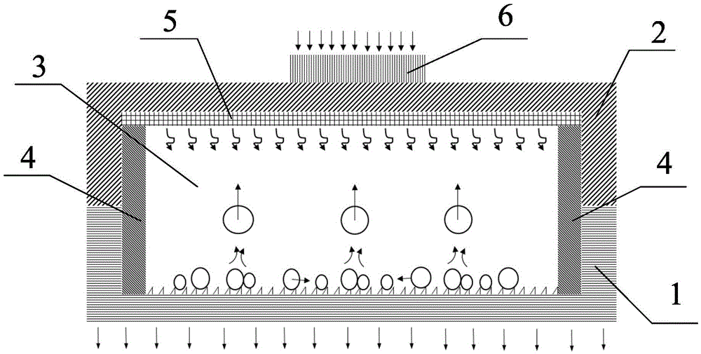
[0026] Such as figure 1 As shown, in this embodiment, a vacuum chamber vapor chamber includes a bottom plate 1 and a cover plate 2 , both sides of the bottom plate 1 and the cover plate 2 are welded and sealed to form a hollow airtight chamber 3 . The airtight chamber 3 is filled with a certain fluid working medium, and the liquid filling rate is 30%-50%. Bottom plate 1 has a superhydrophobic surface and serves as a condensation zone for the vapor chamber of the vacuum chamber. The cover plate 2 has a super-hydrophilic surface and serves as the evaporation zone of the vapor chamber. Copper foam 4 is buried in the airtight cavity 3 with a porosity of 85% to 95%. One end of the copper foam 4 is connected to the cover plate 2 , and the other end of the copper foam 4 is connected to the bottom plate 1 . The microstructure of the porous medium 5 on the copper foam 4 and the cover plate 1 serves as a liquid-absorbing core for promoting the return of the working fluid from the cond...


PUM


Abstract

The invention discloses a vapor chamber, which comprises a bottom plate and a cover plate, wherein the bottom plate and the cover plate are hermetically connected to construct a hollow enclosed cavity; the bottom plate is provided with a super-hydrophobic surface which is taken as the condensing area of the vapor chamber; the cover plate is provided with a super-hydrophilic surface which is taken as the evaporating area of the vapor chamber; foam copper is buried in the enclosed cavity by pressing; one end of the foam copper is connected with the cover plate, and the other end of the foam copper is connected with the bottom plate, thereby facilitating return of a working medium from the condensing area to the evaporating area. According to the vapor chamber, the heat exchange performance of the evaporating area and the condensing area of the vapor chamber is enhanced, the heat exchange capability of the vapor chamber is enhanced by using circular flow of the working medium in the evaporating area and the condensing area, and the heat exchange limit of the vapor chamber is increased.

Description

technical field [0001] The invention relates to a microelectronic device heat dissipation technology, in particular to a vacuum cavity soaking plate. Background technique [0002] With the rapid and rapid progress of modern science and technology such as IT, communications, LED and solar energy, electronic equipment is developing towards multi-function, high-speed, and small-size directions, and the unit calorific value of electronic devices used in them is rapidly increasing. During the actual operation of electronic equipment, with the increase of temperature, the failure rate of electronic components increases exponentially. When the operating temperature range of the component is exceeded, its performance will drop significantly, and it will not work stably, seriously affecting the reliability of the system operation. Studies have shown that if the temperature of a single semiconductor component rises by 10°C, the reliability of the system will decrease by 50%. The dev...

Claims


Application Information

Patent Timeline
Patent Type & Authority Patents(China)
IPC IPC(8): H05K7/20
Inventor 全晓军刘修良郑平
Owner SHANGHAI JIAOTONG UNIV
Why Eureka
Try Eureka