Superconducting wire connection structure, superconducting wire connection method, and superconducting wire for connecting

A connection method and superconducting wire technology, applied in superconducting/high-conducting conductors, usage of superconducting elements, superconducting magnets/coils, etc., can solve problems such as current density increase, superconducting layer degradation, heat generation, etc., and achieve easy connection Effect

Active Publication Date: 2014-03-26
FURUKAWA ELECTRIC CO LTD
View PDF11 Cites 11 Cited by
  • Summary
  • Abstract
  • Description
  • Claims
  • Application Information

AI Technical Summary

Problems solved by technology

[0012] However, in the case of the connection structure of the above-mentioned prior art and Patent Document 1, there are problems as follows: Figure 8B , Figure 8C As shown, in the vicinity of the end of the superconducting wire 100 for connection (the portion surrounded by ...

Method used


Image

  • Superconducting wire connection structure, superconducting wire connection method, and superconducting wire for connecting
  • Superconducting wire connection structure, superconducting wire connection method, and superconducting wire for connecting
  • Superconducting wire connection structure, superconducting wire connection method, and superconducting wire for connecting

Examples


Embodiment Construction

[0047] Hereinafter, preferred modes for carrying out the present invention will be described with reference to the drawings. However, in the embodiments described below, various limitations technically preferable for implementing the present invention are added, but the scope of the present invention is not limited to the following embodiments and illustrated examples.

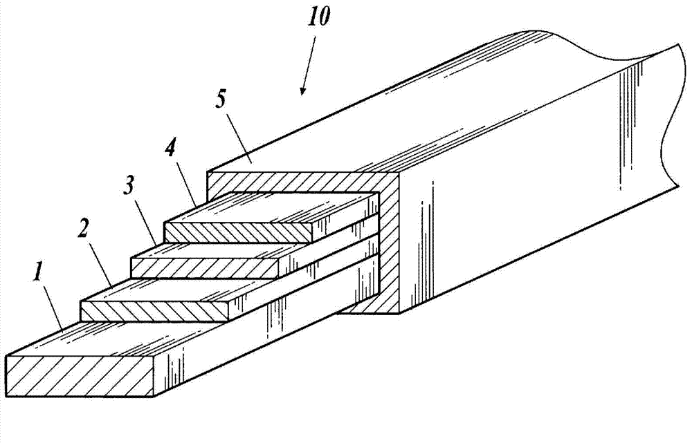
[0048] figure 1 It is an explanatory diagram showing a layer structure of a superconducting wire.

[0049] For example, if figure 1 As shown, the superconducting wire 10 is a tape-shaped superconducting wire, which has: a laminate formed by sequentially laminating an intermediate layer 2, a superconducting layer 3, and a protective layer 4 on a substrate 1; and a stabilization layer covering the periphery of the laminate. 5.

[0050] The substrate 1 is, for example, a strip-shaped metal substrate made of low-magnetic non-oriented metal such as Hastelloy (HASTELLOY, registered trademark).

[0051] The int...


PUM


Abstract

A superconducting wire connection structure is adopted in which, in a section where the ends of a first superconducting wire (11) and a second superconducting wire (12) are spaced apart from and arranged across from each other, the third superconducting wire (13), which is narrower in at least one portion than the first superconducting wire (11) and the second superconducting wire (12), spans and connects the first superconducting wire (11) and the second superconducting wire (12) along the longitudinal direction of the first superconducting wire (11) and second superconducting wire (12). Thereby, it is possible to reduce degradation of the superconducting layer (3) by suppressing generation of heat caused by current flow concentration at the section where the third superconducting wire (13) is connected, and stable superconducting performance can be achieved.

Description

technical field [0001] The present invention relates to a connection structure of a superconducting wire, a method for connecting a superconducting wire, and a superconducting wire for connection. Background technique [0002] In the past, such as Figure 8A , Figure 8B , Figure 8C As shown, when connecting the superconducting wires, the superconducting wires 100 that have been cut short for connection are bonded by welding or spot welding to the portions where the ends of the superconducting wires 10 abut against each other, and then electrically connected. [0003] For example, in Patent Document 1 (refer to Patent Document 1 image 3 ) also discloses the connection structure as described above. [0004] In addition, the following techniques are known: a technique of depositing a superconducting thin film on the portion where the ends of superconducting wires butt against each other by vapor deposition and bonding (see, for example, Patent Documents 2 and 3); A techn...

Claims


Application Information

Patent Timeline
IPC IPC(8): H01B12/06H01B13/00H01F6/06H01R4/68H02G15/34
CPCH01L39/02H02G15/34H01R4/68H01L21/28Y02E40/648H01F6/06H01L39/14Y10T29/49014Y02E40/60H10N60/80H10N60/0296H01B12/02
Inventor 三觜隆治八木正史
Owner FURUKAWA ELECTRIC CO LTD
Why Eureka
Try Eureka