Hematomanometer
A sphygmomanometer, voltage frequency technology, applied in the field of sphygmomanometer, can solve the problems of inability to measure and control, complicated communication process between sphygmomanometer and mobile terminal, etc., and achieve the effects of reducing volume, being easy to carry, and being convenient to use.
- Summary
- Abstract
- Description
- Claims
- Application Information
AI Technical Summary
Problems solved by technology
Method used
Image
Examples
Embodiment 1
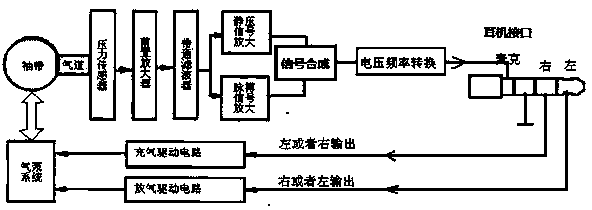
[0053] see figure 1 Shown is a hardware structure diagram of a sphygmomanometer of the present invention.
[0054] Such as figure 1 As shown, a blood pressure monitor includes: a cuff, an airway, a pressure sensor, a signal processor, a voltage-to-frequency converter, an air pump system, and a communication interface;
[0055] The airway is connected to the cuff; the output end of the air pump system is connected to the airway;
[0056] The pressure sensor is arranged in the cuff, and the pressure sensor detects the pulse pressure signal generated by static air pressure and pulse; the output end of the pressure sensor is connected to the input end of the signal processor; the output end of the signal processor is connected to the voltage frequency converter;
[0057] The communication interface is composed of a signal input terminal, a signal output terminal and a ground terminal; the output terminal of the voltage frequency converter is connected to the signal output ter...
Embodiment 2
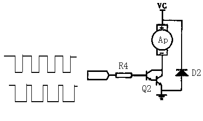
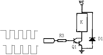
[0062] The air pump system of the sphygmomanometer provided by the invention controls the inflation and deflation of the air pump system through the inflation driving circuit and the deflation driving circuit.
[0063] figure 2 It is the structural diagram of the inflation driving circuit of the air pump system of the present invention.
[0064] see figure 2 As shown, the inflation driving circuit is mainly composed of an air pump AP, a resistor R4, a composite tube Q2 and a diode D2; the output end of the resistor R4 is connected to the base of the composite tube Q2, and the collector of the composite tube Q2 is connected to the air pump AP The negative pole of the air pump AP is connected to the power supply, the emitter of the composite tube Q2 is connected to the positive pole of the diode D2, the negative pole of the diode D2 is connected to the positive pole of the air pump AP, and the emitter of the composite tube Q2 is grounded; The signal input terminal of the le...
Embodiment 3
[0076] Figure 4 It is a signal amplification structure block diagram of the signal processor of the present invention.
[0077] In the sphygmomanometer provided by the present invention, the signal processor includes:
[0078] A preamplifier, the preamplifier receives the static pressure signal and the pulse pressure signal detected by the pressure sensor, amplifies the static pressure signal and the pulse pressure signal as a whole and outputs the amplified signal;
[0079] A band-pass filter, the input end of the band-pass filter is connected to the output end of the preamplifier, and the static pressure amplified signal and pulse pressure amplified signal output by the preamplifier are separated;
[0080] A pulse amplifier, the input end of the pulse amplifier is connected to the output end of the band-pass filter, and the pulse amplifier re-amplifies the pulse pressure amplification signal separated by the band-pass filter;
[0081] A signal synthesizer, the input ...
PUM
 Abstract
Description
Claims
Application Information
 - R&D
- Intellectual Property
- Life Sciences
- Materials
- Tech Scout
- Unparalleled Data Quality
- Higher Quality Content
- 60% Fewer Hallucinations
Browse by: Latest US Patents, China's latest patents, Technical Efficacy Thesaurus, Application Domain, Technology Topic, Popular Technical Reports.
© 2025 PatSnap. All rights reserved.Legal|Privacy policy|Modern Slavery Act Transparency Statement|Sitemap|About US| Contact US: help@patsnap.com


