System for controlling dioxin emission in flue gas in real time and working method thereof

A real-time control and flue gas technology, applied in separation methods, chemical instruments and methods, and dispersed particle separation, etc., can solve problems such as endangering the health of surrounding residents, dioxin super-standard emission, and the inability of online real-time monitoring of activated carbon adsorption capacity.

Inactive Publication Date: 2014-04-02
葛守飞 +2
View PDF4 Cites 2 Cited by
  • Summary
  • Abstract
  • Description
  • Claims
  • Application Information

AI Technical Summary

Problems solved by technology

[0003] The time delay is serious, and when the test results come out, the smoke that exceeds the standard has already been discharged; this kind of test becomes meaningless
[0004] In addition, the current terminal control method for dioxins is mainly to use activated carbon adsorption. The adsorption capacity of activated carbon will gradually decrease with the running time. Since the adsorption capacity of activated carbon cannot be monitored in real time online, in practice it is judged by manual experience. When parameters such as the type or treatment capacity and the production and operation status of the incineration plant change, it is easy to cause dioxins to exceed the standard discharge, which seriously endangers the health of surrounding residents.

Method used


Image

  • System for controlling dioxin emission in flue gas in real time and working method thereof

Examples


Embodiment 1

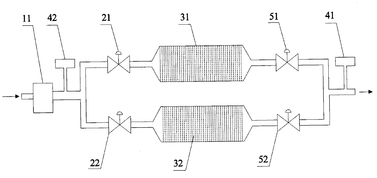
[0034] figure 1 Schematically provides a simplified structural diagram of a system for real-time control of dioxin emissions in flue gas according to an embodiment of the present invention, as figure 1 As shown, the system includes:

[0035] A pretreatment device 11, the pretreatment device 11 is used to remove dust, acidity, and odorous gases in the flue gas; the pretreatment device 11 is a prior art in the art, and will not be repeated here;

[0036] Switching components 21, 22, the switching components 21, 22 are used to selectively connect the outlet of the pretreatment device to any one of the two-way dioxin removal devices; the switching components are specifically: two valves are set, The flow path switching is realized by opening and closing the valve;

[0037] Two road dioxin removal devices, each road dioxin removal device includes: catalytic reactors 31, 32, the catalytic reactors are used to remove dioxins in flue gas, the structure and working principle of the r...

Embodiment 2

[0052] The system for removing dioxins in flue gas online in the embodiment of the present invention is different from Embodiment 2 in that: in each dioxin removal device, a first detector is arranged between the switching part and the reactor, and the reactor and the reactor Second detectors are arranged between the valves.


PUM


Abstract

The invention provides a system for controlling dioxin emission in flue gas in real time and a working method of the system. The system comprises a pre-treating device, a switching part and at least two dioxin removing devices, wherein the pre-treating device is used for removing dust, and acidy and smelly gases in the flue gas; the switching part is used for selectively communicating the outlet of the pre-treating device with one of the at least two dioxin removing devices; each dioxin removing device comprises a reactor, a valve, a first detector, a second detector and a judging module, wherein the reactor is used for removing dioxin in the flue gas; the valve is arranged at the downstream of the reactor; the first detector and the second detector are respectively used for detecting concentration of a dioxin precursor in the flue gas at the upstream and the downstream of the reactor, and outputting the value to the judging module; and the judging module is used for judging that whether switching is needed or not according to the received concentration value, and transmitting the result to the switching part and the valve. The system disclosed by the invention has the advantages of detecting in real time, continuously treating, preventing standard-exceeding emission, and the like.

Description

technical field [0001] The invention relates to dioxin emission control, in particular to a system for real-time control of dioxin emission in flue gas and a working method thereof. Background technique [0002] At present, dioxins are contained in the flue gas produced during the waste incineration process. Dioxins are very complex mixtures containing more than 200 components, which are difficult to detect in real time with online instruments. For example, the current detection method for dioxins is: off-line sampling of flue gas, and then use chromatography, immunoassay, biological method, and laser mass spectrometry for detection, so as to know the content of dioxins in the flue gas. This method has disadvantages, such as: [0003] The time delay is serious, and by the time the test results come out, the smoke that exceeds the standard has already been discharged; this kind of test becomes meaningless. [0004] In addition, the current terminal control method for dioxin...

Claims


Application Information

Patent Timeline
Patent Type & Authority Applications(China)
IPC IPC(8): B01D53/70
Inventor 葛守飞周峻梁涛
Owner 葛守飞
Why Eureka
Try Eureka