Device for conducting electrical discharge machining on outer surface with complex shape

An electrical discharge machining, external surface technology, applied in electric machining equipment, metal machining equipment, electrode manufacturing, etc., can solve problems such as difficulty in meeting actual production needs, forming electrode production, installation difficulty, tool electrode wear, etc., to promote industrial The application and technical means are simple and easy to implement, and the effect of fast processing speed

Active Publication Date: 2014-04-02
SOUTH CHINA UNIV OF TECH
View PDF6 Cites 3 Cited by
  • Summary
  • Abstract
  • Description
  • Claims
  • Application Information

AI Technical Summary

Problems solved by technology

[0005] However, if the traditional shaped electrode discharge machining method is used to process the outer surface with complex shapes, it is required to manufacture a rigid shaped electrode first, because the shaped electrode is quite difficult to manufacture and install, and there are still problems in the EDM process. Wear of the tool electrode, so machining complex-shaped external surfaces by EDM with formed electrodes is time-consuming and expensive
[0006] If wire electric discharge cutting is used to process the outer surface with complex shapes, although it can avoid the problem of costing a lot of cost in the production of forming electrodes, it can also ignore the impact of tool electrode loss on the processing process, but the processing speed of this method is extremely low , it is difficult to meet the needs of actual production

Method used


Image

  • Device for conducting electrical discharge machining on outer surface with complex shape
  • Device for conducting electrical discharge machining on outer surface with complex shape
  • Device for conducting electrical discharge machining on outer surface with complex shape

Examples


Embodiment

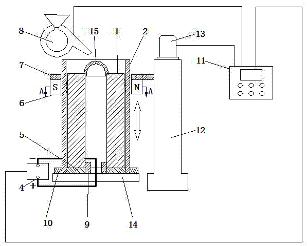
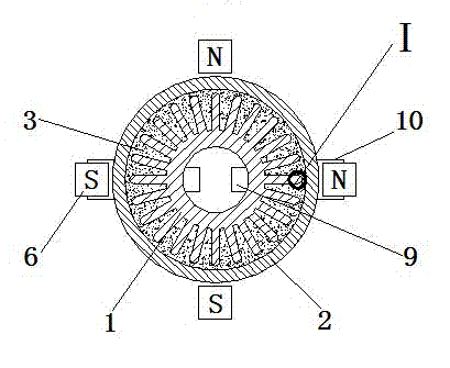
[0030] Such as figure 1 and image 3 As shown, a device for performing electrical discharge machining on a complex-shaped outer surface includes a processing power source 4, a workpiece fixture 9 for clamping a workpiece 1, and also includes:

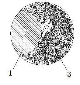
[0031] The outer edge electrode 2 is fixed on the workbench 14 through the electrode fixture 10, and surrounds the outer surface of the workpiece 1 to be processed, and the inner wall of the outer edge electrode 2 is separated from the outer edge of the workpiece 1 by a certain gap

[0032] Feed system 12, one end of the feed system 12 is provided with a motor 13, and the side wall is provided with a magnetic pole clamp 7 that can reciprocate linearly within a predetermined stroke range under the drive of the motor 13;

[0033] The ring-shaped magnetic pole group 6 is fixedly arranged on the magnetic pole holder 7, surrounds the outer wall of the outer edge electrode 2 with a certain gap, and can perform linear reciprocating motion alo...


PUM


Abstract

The invention discloses a device for conducting electrical discharge machining on the outer surface with complex shape. The device comprises a machining power supply and a workpiece clamp used for clamping workpieces and further comprises an outer edge electrode, a feeding system, an annular magnetic pole group and a control system. The outer edge electrode is fixed on the periphery of the outer surface of a workpiece to be machined, and a certain gap is reserved between the inner wall of the outer edge electrode and the outer edge of the workpiece. A motor is arranged at one end of the feeding system, and a magnetic pole clamp capable of reciprocating linearly in the preset journey range under driving of the motor is arranged on the lateral wall of the feeding system. The annular magnetic pole group is fixedly arranged on the magnetic pole clamp and encloses the outer wall of the outer edge electrode with a certain gap reserved in between. The control system is connected with the motor and the machining power supply through a circuit, two electrodes of the machining power supply are connected with the workpiece and the outer edge electrode, and conductive magnetic powder is arranged between the outer edge electrode and the outer surface of the workpiece to be machined. The device can be used for conducting coarsening, modification, strengthening and the like on the outer surface with the complex shape, can also be used for coating the outer surface with the complex shape, and is high in efficiency and low in cost.

Description

[0001] technical field [0002] The invention belongs to the field of electrical machining, and in particular relates to a device for electrical discharge machining of complex-shaped outer surfaces. Background technique [0003] With the development of economy and technology, various devices with complex-shaped outer surfaces have been widely used in production and life. Studies have shown that the secondary processing of the outer surface of such devices, such as on the outer surface of the device Manufacturing various microstructures, strengthening the outer surface of the device, or forming a coating on the outer surface of the device can effectively improve the function of this type of device, which has great practical significance. For example, if it can be applied to various The outer surface of the heat sink in the industrial field has a tiny structure, which can effectively increase the heat transfer surface area, thereby effectively improving the heat transfer effic...

Claims


Application Information

Patent Timeline
Patent Type & Authority Applications(China)
IPC IPC(8): B23H1/00B23H1/04B23H1/08
Inventor 刘江文郭钟宁孙书伟陈日
Owner SOUTH CHINA UNIV OF TECH
Why Eureka
Try Eureka