Workpiece pressing device and drill press workbench with same

A technology of pressing device and worktable, applied in positioning devices, manufacturing tools, metal processing machinery parts, etc., can solve the problems of reduced versatility of pressing devices, deformation of moving guide rails, inability to meet customers, etc., and achieves easy loading of workpieces, The effect of stable and flexible movement

Active Publication Date: 2014-04-02
ZHEJIANG XILING
View PDF6 Cites 10 Cited by
  • Summary
  • Abstract
  • Description
  • Claims
  • Application Information

AI Technical Summary

Problems solved by technology

The hydraulic cylinder is installed on the moving guide rail. Although it can adjust the position of the hydraulic cylinder and ensure the smooth movement of the hydraulic cylinder, the allowable loading force is relatively small. The reason is that the moving guide rail is deformed due to excessive force.
The current usual practice of those skilled in the art is to increase the maximum load of the moving guide rail or to fix the oil cylinder on the workbench. The former method leads to an increase in production cost and volume, which makes the drilling machine lose its competitiveness and is finally eliminated by the market; This approach leads to a reduction in the versatility of the compression device, which cannot meet the needs of customers, and is finally eliminated by the market.
In short, the current pressing device that uses an oil cylinder as the driving force is only suitable for pressing small workpieces, and cannot meet the needs of pressing large workpieces.

Method used


Image

  • Workpiece pressing device and drill press workbench with same
  • Workpiece pressing device and drill press workbench with same
  • Workpiece pressing device and drill press workbench with same

Examples


Embodiment 1

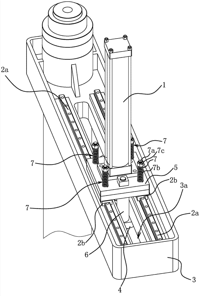
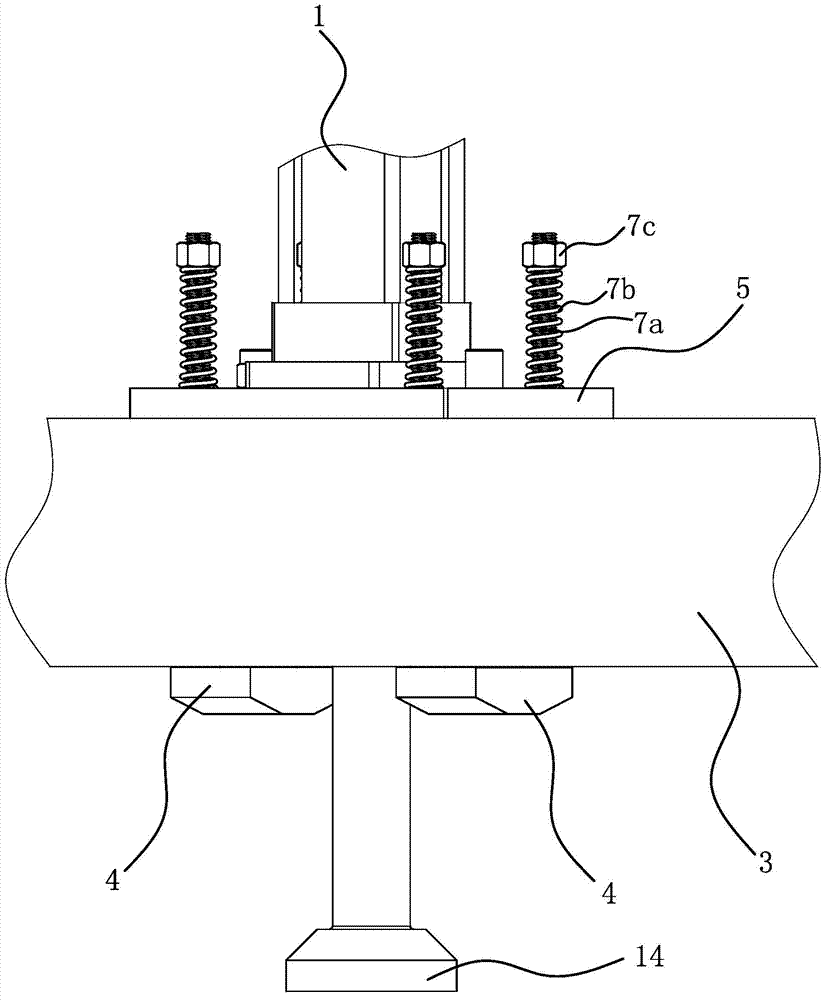
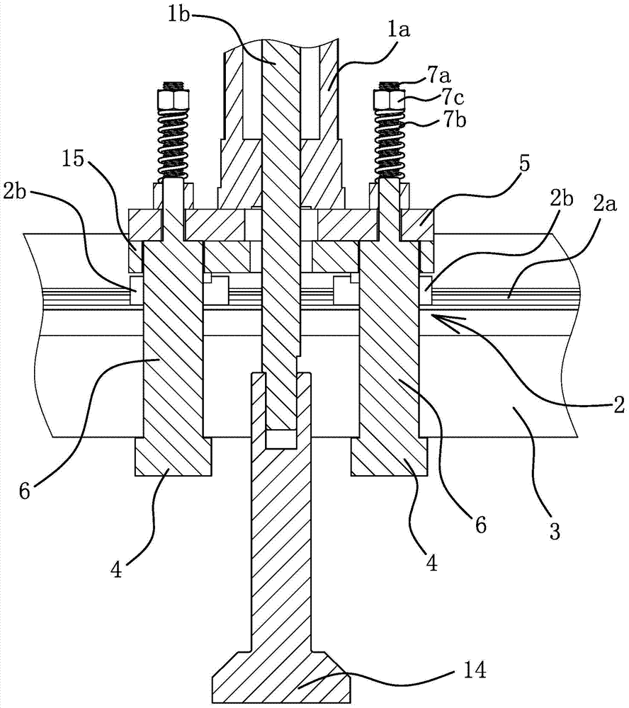
[0029] Such as figure 1 with figure 2 As shown, the workpiece pressing device includes an oil cylinder 1, a guide rail 2a assembly 2, a pressing arm 3, a pressure receiving block 4 and a connecting plate 5.

[0030] Cylinder 1 is a pressure source that applies pressure to the workpiece. Adopting the oil cylinder 1 as the pressure source has the advantages of stable feed, high pressure that can be applied to the workpiece and long-term pressure stability.

[0031] The pressing arm 3 is a basic component for other components to be installed, and is also a force bearing component.

[0032] The guide rail 2 a of the guide rail assembly 2 is fixedly connected with the pressing arm 3 ; all the sliders 2 b of the guide rail assembly 2 are connected with the connecting plate 5 . The cylinder body 1a of the oil cylinder 1 is fixedly connected with the connecting plate 5; the pressure receiving block 4 and the connecting plate 5 are located on both sides of the pressing arm 3 respec...

Embodiment 2

[0046] The structure and principle of this embodiment are basically the same as those of the first embodiment, except that the pressing arm 3 and the base 8 are connected by a fixed connection structure. The fixed connection structure includes a column 10 , the base 8 has a column connecting seat 11 , the pressing arm 3 is fixedly connected to the upper end of the column 10 , and the lower end of the column 10 is fixedly connected to the column connecting seat 11 .


PUM


Abstract

The invention provides a workpiece pressing device and a drill press workbench with the same, belongs to the technical field of operation, and solves the problem that the existing pressing device cannot meet requirements of pressing large workpieces. The workpiece pressing device comprises an oil cylinder, a guide rail assembly, a pressing arm, compression blocks and connection plates. The compression blocks and the connection plates are located on two sides of the pressing arm respectively and are fixedly connected with each other. Guide rails of the guide rail assembly are fixedly connected with pressing arm. A cylinder body of the oil cylinder is fixedly connected with the connection plates. All sliding blocks of the guide rail assembly are connected with the connection plates. The guide rail assembly is used for guiding when the oil cylinder is moved so that the workpiece pressing device has the advantages of being stable and flexible in motion. When the workpiece pressing device is used for pressing workpieces, the compression blocks butt against the pressing arm to bear the reactive force, and damage of the guide rail assembly caused by overlarge stress on the guide rail assembly can be avoided. In shorts, the workpiece pressing device can improve the maximum workpiece pressure exerting value and can be provided with the guide rail assembly with low bearing capacity.

Description

technical field [0001] The invention belongs to the technical field of operations, and relates to a workpiece fixing device, in particular to a workpiece pressing device. [0002] The invention belongs to the field of operation technology, and relates to a workbench, in particular to a drilling machine workbench with a workpiece pressing device. Background technique [0003] Drilling machine refers to a machine tool that mainly uses a drill bit to process holes in a workpiece. The characteristic of the drilling machine is that the workpiece is fixed and the tool rotates. In other words, during the machining process, the workpiece is fixed on the worktable by the fixture, the tool is moved, the center of the tool is aligned with the center of the hole, and the tool is rotated. [0004] In order to achieve a stable fixation of the workpiece and fix it in a proper position, different fixtures have been designed. General fixtures such as machine vises, chucks, suction cups, d...

Claims


Application Information

Patent Timeline
Patent Type & Authority Applications(China)
IPC IPC(8): B23Q3/06B23Q1/25
CPCB23Q1/25B23Q3/069B23Q3/082
Inventor 毛益波
Owner ZHEJIANG XILING
Why Eureka
Try Eureka