
Round stick processing machinery

A technology for processing machinery and round wood bars, which is applied in the field of processing machinery for processing round wood bars of different specifications, can solve the problems of unadjustable feeding speed of round bar machines, reduced product qualification rate, complicated operation, etc., so as to ensure the utilization rate of raw materials, Increase the processing range and eliminate the effect of gap shaking

Inactive Publication Date: 2014-04-02
山西晟龙木雕模型艺术有限公司
View PDF9 Cites 17 Cited by
  • Summary
  • Abstract
  • Description
  • Claims
  • Application Information

AI Technical Summary

Problems solved by technology

Although most of the rotary cutterheads of existing round bar machines are equipped with dovetail guide grooves, there are still the following deficiencies and problems: 1. The fixing screws of the two cutters must be loosened each time, and the cutter and the cutter bracket should be taken together. Then unscrew the feed hole and replace it with a feed hole of the required specification, then install the cutter and carefully adjust the parameters such as the cutting amount of the cutter, the operation is cumbersome
2. When adjusting the amount of cutter engagement and the feeding hole, only the two-dimensional adjustment of the two cutters can be performed.
3. Affected by adjustment and tool wear, the surface of the processed round wooden sticks is rough. If there is a certain requirement for the smoothness of the round wooden sticks, a grinding and polishing process must be done
4. The feeding speed of the round bar machine cannot be adjusted. Due to the different densities of various woods, the required feeding speed is also different. If the feeding is carried out at one speed, either the efficiency is low or the product qualification rate is reduced.
Therefore, the existing wooden round bar machine is only suitable for mass production of round wooden bars of the same specification, and is not suitable for occasions where the processing specifications are diverse and the cutting tool needs to be changed frequently.

Method used


Image

  • Round stick processing machinery
  • Round stick processing machinery
  • Round stick processing machinery

Examples


Embodiment Construction

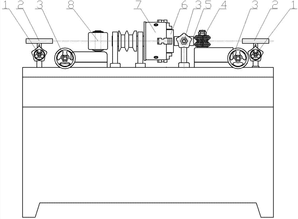
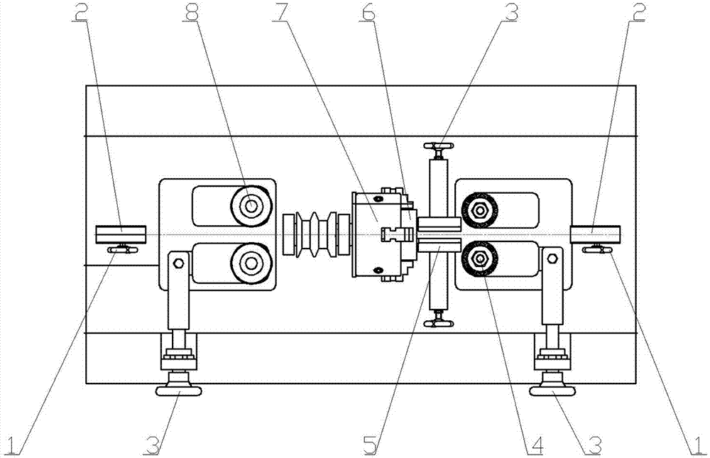
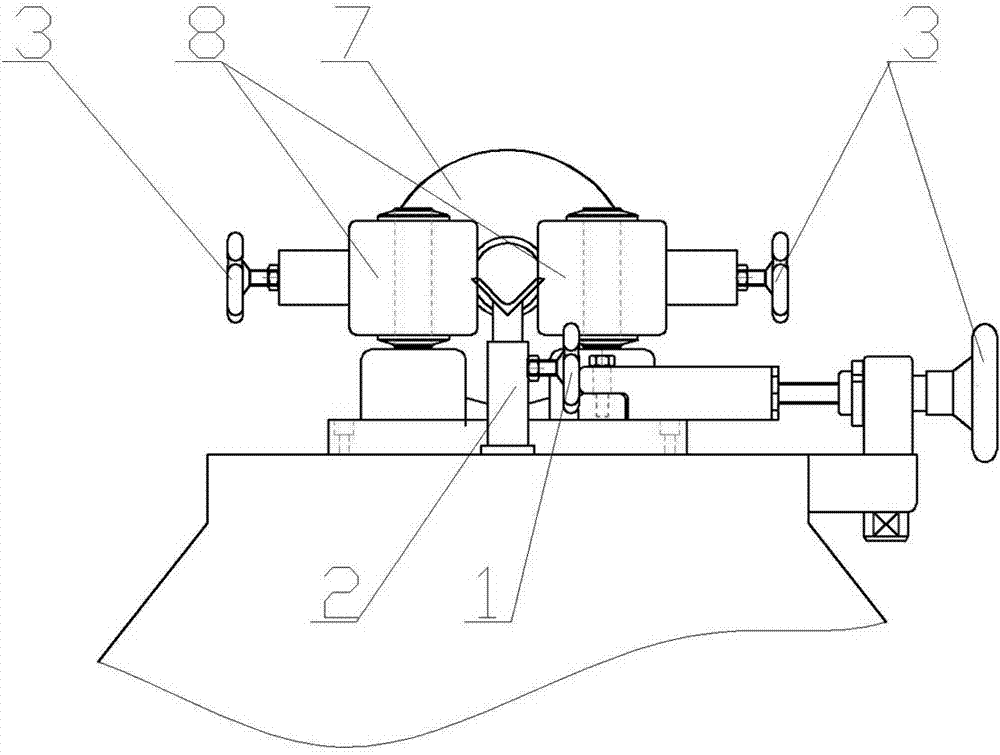
[0020] The structure of round wood rod processing machinery is as follows: figure 1 , 2 , 3 and 4 are composed of a support frame 2 installed on the workbench of the round wood processing machine, a feed clamping roller 4, a V-shaped guide clamp 5, a processing tool 6, a three-claw disc 7 and a dial wheel 8. .

[0021] The structure of processing tool 6 is as Figure 5 , the center of the tool is a material passing hole 9 matching the diameter of the round wooden rod to be processed, and the front end of the tool is provided with cutter teeth 10. The processing tool 6 is fixed at the axis position of the three-jaw disc 7 .

[0022] The front and rear ends of the workbench are respectively provided with support racks 2 for lifting the wooden sticks to be processed and the processed round wooden sticks. The support rack 2 is provided with a support rack adjustment hand wheel 1 for adjusting the position of the support rack. .

[0023] The place ahead of processing tool 6 is...


PUM


Abstract

The invention discloses round stick processing machinery, wherein a processing cutter is fixed on the axle center position of a three-jaw chuck, a material passing hole matched with the diameter of a round stick is formed in the center, cutter teeth are arranged on the front end, feeding and clamping rollers are a pair of rollers provided with 90-degree V-shaped grooves located in the front end of the processing cutter and are used for conveying a batten to be processed, a material shifting wheel is located on the rear end of the processing cutter and is used for outputting a processed round stick, and material brackets used for supporting the batten to be processed and the processed round stick are respectively arranged on the front end of each feeding and clamping roller and on the rear end of the material shifting wheel. According to the round stick processing machinery disclosed by the invention, the processing cutter does not need to be adjusted, and processing cutters with different specifications are directly changed to process round sticks with different specifications. The round stick processing machinery disclosed by the invention can be used for processing a round stick with a minimal diameter of only 1 mm.

Description

technical field [0001] The invention relates to a woodworking machine, in particular to a processing machine for processing round wooden sticks of different specifications. Background technique [0002] At present, the wooden round bar machine that can be seen and used in the market has two separate mechanisms, the feeding hole and the cutter. Cooperate with the feeding hole to complete the processing of round wooden rods of different thicknesses. Although most of the rotary cutterheads of existing round bar machines are equipped with dovetail guide grooves, there are still the following deficiencies and problems: 1. The fixing screws of the two cutters must be loosened each time, and the cutter and the cutter bracket should be taken together. Then unscrew the feeding hole and replace it with the feeding hole of the required specification, then install the cutter and carefully adjust the parameters such as the cutting amount of the cutter, the operation is cumbersome. 2. W...

Claims


Application Information

Patent Timeline
IPC IPC(8): B27C5/08
Inventor 刘晓辰
Owner 山西晟龙木雕模型艺术有限公司
Learn More