Double-temperature condensing two-stage compressing heat pump system

A two-stage compression and heat pump system technology, applied in the field of heat pumps, can solve the problems of large heat transfer temperature difference, large compressor compression ratio, large energy loss, etc., to reduce exhaust temperature, reduce energy loss, and reduce heat transfer temperature difference. Effect

Inactive Publication Date: 2014-04-02
UNIV OF SHANGHAI FOR SCI & TECH
View PDF7 Cites 4 Cited by
  • Summary
  • Abstract
  • Description
  • Claims
  • Application Information

AI Technical Summary

Problems solved by technology

[0002] Traditional heat pump technology: The operating temperature difference of a single-stage compression heat pump with pure working fluid is generally about 40-50 degrees Celsius. When the temperature difference is large, the compression ratio of the compressor is large and the efficiency is low. The technical characteristics of the system limit the single-stage compression. Application of type heat pump in low temperature environment
A simple self-cascading heat pump system can work under a large temperature difference, but its heat transfer agent only achieves temperature rise in a single condenser, and the initial stage of temperature rise results in a large energy loss due to the large heat transfer temperature difference, and there is only a single evaporator and The corresponding evaporation temperature cannot realize the effective utilization of different grades of low-temperature heat sources
A simple two-stage compression heat pump can also work under a large temperature difference, but there are also problems such as a single condenser with a large heat transfer temperature difference in the initial stage of temperature rise and a single evaporator that cannot realize the effective utilization of low-temperature heat sources of different grades
[0003] Existing patented heat pump technology: the patent number is 200520025920.5, and the name is "Dual Condensation Cascade Heat Pump". This heat pump technology uses part of the heat in the condensing evaporator to heat the low-temperature heat carrier to achieve double condensation. It is difficult to adjust the heat distribution with the low-temperature condenser, and it is difficult to use a single evaporator to realize the effective utilization of low-temperature heat sources of different grades
The patent number is 200410077681.8, and the title is "A Self-Cascade Air Source Heat Pump Water Heater". This patented technology cannot realize dual-temperature condensation and dual-temperature evaporation. The heat transfer temperature difference is large in the initial stage of temperature rise, and the energy loss is large.
Patent No. 200620068100.9, titled "Large Temperature Difference Self-Cascade Heat Pump with Separate Condenser", this patented technology also cannot realize dual-temperature condensation, and the heat transfer temperature difference is large in the initial stage of temperature rise

Method used


Image

  • Double-temperature condensing two-stage compressing heat pump system
  • Double-temperature condensing two-stage compressing heat pump system

Examples


Embodiment 1

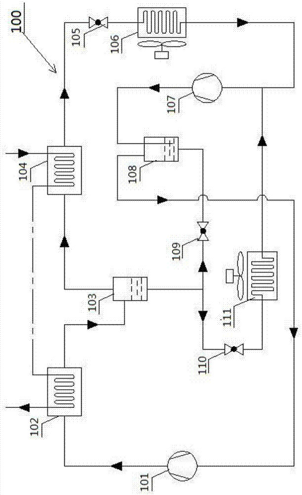
[0023] figure 1 It is a schematic diagram of the overall structure of the dual-temperature condensation two-stage compression heat pump system in Embodiment 1.

[0024] like figure 1 As shown, the decondensation single-temperature evaporation heat pump system 100 includes: a high-pressure stage compressor 101, a high-temperature stage condenser 102, a dephlegmator 103, a low-temperature stage condenser 104, a first throttle valve 105, a low-temperature stage evaporator 106, a low-pressure Stage compressor 107, heat exchanger 108, second throttle valve 109, third throttle valve 110, high temperature stage evaporator 111 and connecting pipelines.

[0025] The outlet of the high-pressure stage compressor 101 is connected with the high-temperature stage condenser 102, and the high-temperature stage condenser 102 is connected with the decondenser 103. It is connected with the second throttle valve 109 and the third throttle valve 110 respectively, the low temperature stage conden...

Embodiment 2

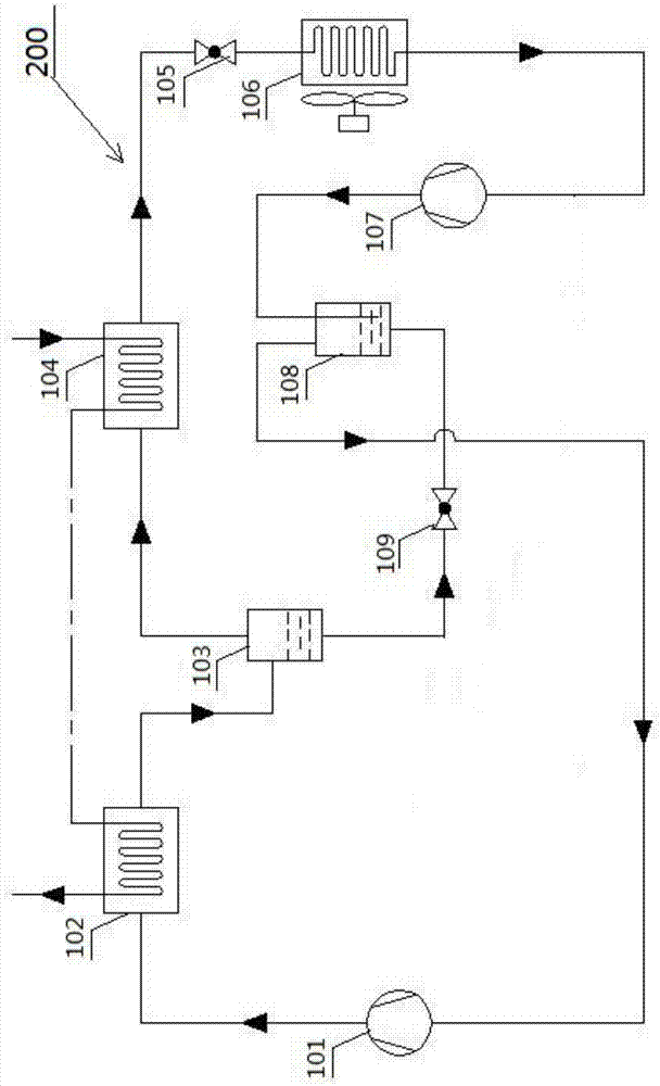
[0035] figure 2 It is a schematic diagram of the overall structure of the dual-temperature condensation two-stage compression heat pump system in Embodiment 1.

[0036] In the second embodiment, the same structures as those in the first embodiment are given the same numbers, and the same descriptions are omitted.

[0037] Such as figure 2 As shown, the dual-temperature condensation two-stage compression heat pump system 200 removes the branch circuit composed of the third throttle valve 110 and the high-temperature stage evaporator 111 on the basis of the first embodiment.

[0038] The function and effect of embodiment two:

[0039] Compared with Embodiment 1, this Embodiment 2 removes the branch structure composed of the high-temperature stage evaporator 111 and the third throttle valve 110 on the basis of Embodiment 1, and only has one evaporator 106, so this embodiment The structure of the second embodiment is more compact, and the function and effect of the second emb...


PUM


Abstract

The invention provides a double-temperature condensing two-stage compressing heat pump system. The double-temperature condensing two-stage compressing heat pump system is characterized by comprising a high pressure stage compressing mechanism, a low pressure stage compressing mechanism, a high temperature stage condensing mechanism, a low-temperature stage condensing mechanism, a high temperature stage evaporation mechanism, a low temperature stage evaporation mechanism, a frictional condensing mechanism, a heat exchanging mechanism, a first throttle mechanism, a second throttle mechanism and a third throttle mechanism; the high pressure stage compressing mechanism, the high temperature stage condensing mechanism, the frictional condensing mechanism, the low temperature stage condensing mechanism, the first throttle mechanism, the low temperature stage evaporation mechanism, the low pressure stage compressing mechanism and the heat exchanging mechanism are sequentially connected to form into a loop; the frictional condensing mechanism is connected with the second throttle mechanism and the third throttle mechanism; the third throttle mechanism is connected with the high pressure stage evaporation mechanism; the high pressure stage evaporation mechanism is connected with the low pressure stage compressing mechanism; the second throttle mechanism is connected with the heat exchanging mechanism. The double-temperature condensing two-stage compressing heat pump system has the advantages of reducing energy loss, improving stability of system operation, meanwhile enabling low temperature heat source in different stages to be used and enabling heat of a low temperature condensing mechanism to be fully used.

Description

technical field [0001] The invention relates to heat pump technology, in particular to a dual-temperature condensation and two-stage compression heat pump system. Background technique [0002] Traditional heat pump technology: The operating temperature difference of a single-stage compression heat pump with pure working fluid is generally about 40-50 degrees Celsius. When the temperature difference is large, the compression ratio of the compressor is large and the efficiency is low. The technical characteristics of the system limit the single-stage compression. Application of type heat pump in low temperature environment. A simple self-cascading heat pump system can work under a large temperature difference, but its heat transfer agent only achieves temperature rise in a single condenser, and the initial stage of temperature rise results in a large energy loss due to the large heat transfer temperature difference, and there is only a single evaporator and The corresponding ...

Claims


Application Information

Patent Timeline
Patent Type & Authority Applications(China)
IPC IPC(8): F25B30/02
Inventor 邱金友张华
Owner UNIV OF SHANGHAI FOR SCI & TECH
Why Eureka
Try Eureka