
Method for measuring occurrence of non-contact structural surface

A measurement method, non-contact technology, applied in the direction of measuring devices, measuring angles, surveying and navigation, etc., can solve the problems that the geological compass is greatly affected by magnetic interference, it is difficult to ensure that the measured value is consistent with the objective true value, and the operation process of the instrument is complicated.

Inactive Publication Date: 2014-04-02
广西华锡集团股份有限公司
View PDF6 Cites 31 Cited by
  • Summary
  • Abstract
  • Description
  • Claims
  • Application Information

AI Technical Summary

Problems solved by technology

[0003] (1) Poor measurement accuracy
[0004] At the engineering site, it is usually to measure an exposed part of the structural surface, and the integrity of the structural surface is not enough, so it is difficult to ensure that the measured value is consistent with the objective true value; for small rock outcrops, it is also difficult to use a geological hammer. If a contact surface of sufficient size is drilled, it will be difficult for the traditional geological compass to make effective contact with the rock surface, and errors in the measurement values ​​will inevitably occur; in addition, manual errors may also be caused due to human hand shake, observation line of sight habits, and light environment.
[0005] (2) Strong magnetic interference from minerals
[0006] When measuring rock formations containing magnetic minerals, the geological compass is subject to strong magnetic interference, making it difficult to accurately measure the occurrence of structural planes
[0007] (3) It cannot be applied to the measurement of some long-distance or difficult-to-reach structural surfaces
[0008] The traditional geological compass measurement method is contact measurement. For structural surfaces under complex conditions, such as cliffs, river obstructions, and high-altitude structural roofs in mines, it is difficult for surveyors to directly contact and measure. The method of virtual extension of structural surfaces is adopted. The influence of factors is serious, and it is difficult to avoid a large deviation between the measured value and the objective true value
[0009] In order to overcome the limitation of contact measurement with mechanical geological compass, William C.Haneberg established a three-dimensional model of rock slope by using digital close-range photogrammetry technology and carried out structural surface mapping work. Liu Zixia carried out a digital close-range photogrammetry based Research on the application of rapid acquisition of rock mass discontinuity information. S.Slob studied the method of measuring rock mass discontinuity based on 3D laser scanning technology. Zhang Wen proposed a rock mass structure information processing method based on 3D laser scanning technology and carried out engineering application, Berger et al. used the SPOT satellite stereo image pair to conduct research on the extraction of the occurrence of surface strata, Liu Huaguo et al. carried out the research work on the extraction of near-surface strata occurrence using remote sensing image technology, and Wang Biao applied GPS technology to near-level In the precise measurement of formation occurrence, these technologies have greatly improved the measurement accuracy and speed, but the operation process of the instrument is complicated, or the equipment is bulky or expensive, and it is difficult to apply it on a large scale
Ma Qingxun invented a geological compass based on the principle of laser linear transmission, but the compass is still contact-type, and it is difficult to avoid the interference of mineral magnetism, and the special occurrence structure plane is not considered

Method used


Image

  • Method for measuring occurrence of non-contact structural surface
  • Method for measuring occurrence of non-contact structural surface
  • Method for measuring occurrence of non-contact structural surface

Examples


Embodiment Construction

[0035] The technical solution of the present invention will be described in further detail below in conjunction with the accompanying drawings and derivation formulas.

[0036] The main effect of the present invention is to use a non-contact method to measure the occurrence of the structural surface, and there are no strict restrictions on the position and angle of the measuring point and the size of the structural surface. The specific operation steps are as follows:

[0037] (1) Place the laser or infrared rangefinder along with the measuring instrument on the station, and the station can be selected arbitrarily without affecting the beam emission and reception.

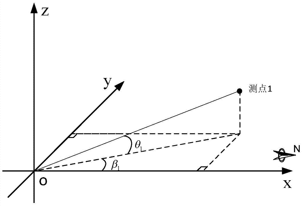
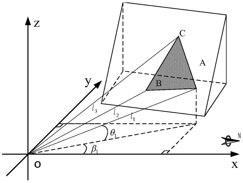
[0038] (2) if figure 1 As shown, take the station of the instrument as the origin of the coordinate system, take the positive direction of the x-axis as the magnetic north direction, and then determine the y-axis and z-axis according to the right-hand rule to establish a spatial Cartesian rectangular coordinate sys...


PUM


Abstract

The invention discloses a method for measuring the occurrence of a non-contact structural surface. The method comprises the following steps: establishing a descartes rectangular coordinate system of a right-hand space by taking a relocation site of a distance meter as an original point and a magnetic north direction as the positive direction of the x-axis by means of a space ranging function of a laser or infrared distance meter; rotating the distance meter to enable a measured light beam to be irradiated to three non-colinear points of a structural surface to be measured, and respectively recording the vertical rotation angle, horizontal rotation angle and measuring distance of each measured light beam; and quantitatively describing the inclination state of the structural surface to be measured by utilizing the relationship between a spatial vector and a geometric projection, and calculating the inclination angle, inclination and trend of the structural surface. By using the method, the application restrict for the contact measurement of the traditional geological compass is broken, the measurement for the occurrence of a long-distance or difficultly-contact structural surface is realized, and the measurement errors caused by the magnetism of minerals are effectively avoided.

Description

technical field [0001] The invention relates to a method for measuring the occurrence of a structural surface, in particular to a non-contact method for measuring the occurrence of a structural surface, which can measure the occurrence of the structural surface at a long distance without contacting the structural surface. Background technique [0002] The occurrence of structural planes includes three elements: strike, dip and dip. The traditional structural plane occurrence measurement uses a geological compass, which usually has the following disadvantages: [0003] (1) Poor measurement accuracy [0004] At the engineering site, it is usually to measure an exposed part of the structural surface, and the integrity of the structural surface is not enough, so it is difficult to ensure that the measured value is consistent with the objective true value; for small rock outcrops, it is also difficult to use a geological hammer. If a contact surface of sufficient size is drille...

Claims


Application Information

Patent Timeline
IPC IPC(8): G01C1/00
CPCG01C1/00
Inventor 吴乐文陈庆发张亚南莫载斌
Owner 广西华锡集团股份有限公司
Learn More