
Electronic load device and simulation method thereof

A technology of electronic load and simulation method, which is applied in the direction of power supply testing, improvement of basic electrical components, etc., can solve problems such as increased hardware investment costs, errors in analog-to-digital converters, and differences in output current waveforms, so as to save hardware equipment and eliminate The effect of accumulating errors and reducing equipment costs

Active Publication Date: 2014-04-02
ITECH ELECTRONICS NANJING
View PDF7 Cites 3 Cited by
  • Summary
  • Abstract
  • Description
  • Claims
  • Application Information

AI Technical Summary

Problems solved by technology

However, this method first needs to use two hardware equipment analog-to-digital converters to simultaneously collect the input voltage value and input current value of the electronic load device, which has the problem of increasing the investment cost of the hardware. In addition, the more serious problem is that the analog-to-digital converter There will be errors in the measurement process. Since the errors will accumulate on the output over time, the output current waveform with load after a long time will be quite different from the ideal simulation model.

Method used


Image

  • Electronic load device and simulation method thereof
  • Electronic load device and simulation method thereof
  • Electronic load device and simulation method thereof

Examples


Embodiment Construction

[0023] Preferred embodiments of the present invention will be described in detail below in conjunction with the accompanying drawings.

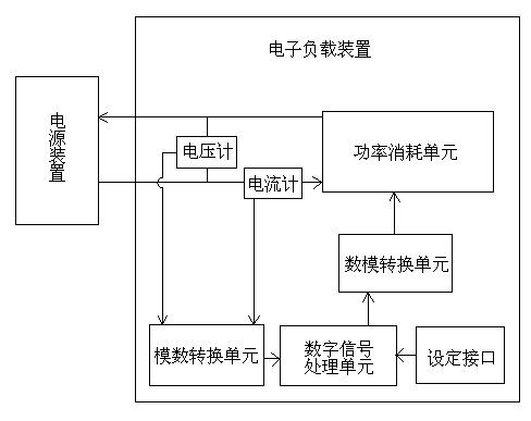
[0024] Example image 3 , Figure 4 and Figure 5 As shown, this embodiment provides an electronic load device for simulating a circuit unit and performing a load test on a power supply device. The electronic load device includes: a power consumption unit, a digital signal processing unit, an analog-to-digital conversion unit, A digital-to-analog conversion unit, a setting interface and a voltage measurement unit.

[0025] The power consumption unit is connected to the power supply unit and has an adjustable current loading function to load the power supply unit;

[0026] The voltage measurement unit is a voltmeter, which is connected between the power consumption unit and the power supply device, and measures the first time voltage value of the power consumption unit's load input to the power supply device at the first time;...


PUM


Abstract

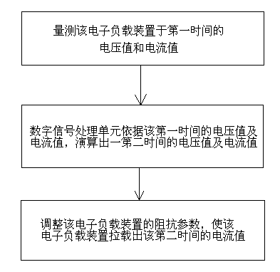
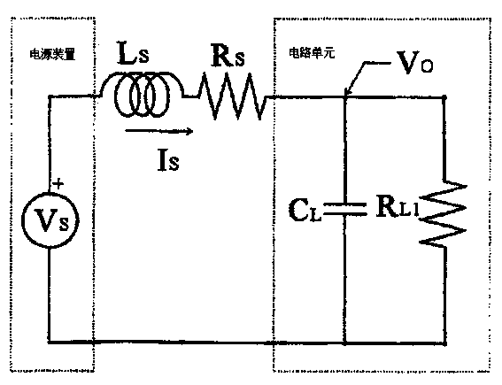
The invention provides an electronic load device and a simulation method thereof. The electronic load device is used for simulating a circuit unit to carry out a loading test on a power supply device. A power consumption unit is connected with the power supply device to load the power supply device; a voltage measurement unit is connected between the power consumption unit and the power supply device and measures a first-time voltage value inputted by the power consumption unit loading the power supply device at a first time; a digital signal processor unit stores and sets the impedance parameter of the circuit unit, receives the first-time voltage value measured by the voltage measurement unit, utilizes the mathematical model of the circuit unit to work out a current value according to a first-time input current value of the first time, then works out a second-time voltage value and a second-time current value according to the impedance parameter of the circuit unit and then outputs an impedance modulation signal to the power consumption unit, so that on-load current is outputted and regulated. Hardware equipment is saved, the circuit structure is simplified, the equipment cost is reduced, and accumulated errors are eliminated.

Description

technical field [0001] The invention relates to an electronic load device, in particular to a simulation method suitable for carrying out a load test on a power supply device. Background technique [0002] Power supply unit is a kind of common electronic equipment, which is widely used in various fields of industry, information communication and social life. Therefore, the rational design and manufacture of power supply unit and other equipment is particularly important. [0003] The electronic load device is a device that makes the power tube dissipate power and consume electric energy by controlling the conduction of the internal power device MOSFET or transistor. Electronic load devices generally have multiple modes of constant current, constant voltage, constant resistance, constant power, short circuit and dynamic load, which can simulate various load conditions. Electronic loads are designed for higher power load equipment such as power supply equipment, etc. A new ty...

Claims


Application Information

Patent Timeline
IPC IPC(8): G01R1/20G01R31/40
Inventor 马海波
Owner ITECH ELECTRONICS NANJING
Learn More